
A4 Cabriolet Mk2
 Note
Note
Note
Note
|
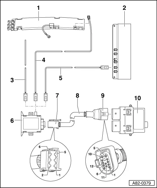
| 1 - | Rear window aerial module |
| q | Designation in current flow diagram depends on vehicle equipment (e.g. aerial -R11- or telephone aerial -R65-) |
| q | On Saloon (and Coupe) |
| q | For vehicles with auxiliary heater remote control unit with additional outgoing circuit → Parts List |
| q | Fitting location → Radio, telephone, navigation; Rep. Gr.91 |
| 2 - | Left aerial module -R108- |
| q | For Avant |
| q | For vehicles with auxiliary heater remote control unit with additional outgoing circuit (marked e.g. “TS”) → Parts List |
| q | Fitting location → Radio, telephone, navigation; Rep. Gr.91 |
| 3 - | Aerial wire with aerial |
| q | Designation in current flow diagram is governed by vehicle equipment |
| q | For Cabriolet |
| q | Only installed on vehicles with auxiliary heater remote control unit → Parts List |
| q | Routed in boot lid → Radio, telephone, navigation; Rep. Gr.91 |
| 4 - | Aerial wire from aerial module to auxiliary heating radio controlled receiver -R64- |
| q | On Saloon (and Coupe) |
| 5 - | Aerial wire from aerial module to auxiliary heating radio controlled receiver -R64- |
| q | For Avant |
| 6 - | Auxiliary heating radio controlled receiver -R64- |
| q | Transmits appropriate information to auxiliary heater control unit -J364- on reception of remote control signals (activation or deactivation of auxiliary heating/auxiliary ventilation) |
| q | Can be deactivated by auxiliary heater control unit -J364- (thus reducing no-load current input) → Chapter (Reading measured value block, display group “007”) |
| q | Checking signals from auxiliary heating radio controlled receiver -R64- → Chapter |
Note| t | The remote control hand transmitter is adapted in the auxiliary heating radio controlled receiver -R64- and not in the auxiliary heater control unit -J364- → Chapter (Adaption, adaption channel “004”). |
| t | The remote control hand transmitter signals are only relayed by the auxiliary heating radio controlled receiver -R64-. The auxiliary heater control unit -J364- then processes the signals → Chapter (Reading measured value block, display group “007”). |
| t | If the auxiliary heating radio controlled receiver -R64- is replaced, all hand transmitters have to be adapted → Chapter (the remote control hand transmitters are assigned in the auxiliary heating radio controlled receiver -R64- by way of the auxiliary heater control unit -J364-). |
| 7 - | 6-pin connector to auxiliary heating radio controlled receiver -R64- |
| q | Contact “1” |
| – | Output for ON and OFF signal to auxiliary heater control unit -J364- → Chapter |
| – | If the receiver is in power saving mode, no signal is supplied after/on pressing the remote control ON or OFF button → Chapter |
| q | Contacts “2”, “3” and “5” |
| – | Not used |
| q | Contact “4” |
| – | Earth |
| q | Contact “6” |
| – | Power supply (terminal “30”) |
| 8 - | Wiring to auxiliary heater control unit -J364- |
| q | Incorporated into vehicle wiring harness → Current flow diagrams, Electrical fault finding and Fitting locations |
| 9 - | 12-pin connector to auxiliary heater control unit -J364- |
| q | Contact “1” |
| – | From auxiliary heating radio controlled receiver -R64- to input for ON and OFF signal in auxiliary heater control unit -J364- → Chapter |
| q | If the receiver is in power saving mode, no signal is supplied after/on pressing the remote control ON or OFF button → Chapter |
| q | Procedure for electrical checks at connector → Chapter |
| q | Further pin assignment → Chapter and → Current flow diagrams, Electrical fault finding and Fitting locations |
| 10 - | Auxiliary heater control unit -J364- |
| q | Adaption of remote control hand transmitter in auxiliary heater control unit -J364- → Chapter (Adaption, adaption channel “004”) |
| q | If auxiliary heating/auxiliary ventilation is implemented by way of remote control, the operating and display unit, Climatronic control unit -J255- or the control unit in dash panel insert -J285- determines whether “auxiliary heating” or “auxiliary ventilation” mode is activated → Chapter |
Note| t | At present, a maximum of 4 remote control units can be adapted in the auxiliary heating radio controlled receiver -R64- (by way of the auxiliary heater control unit -J364-). Adaption of a fifth remote control unit causes the first matched remote control to be erased. |
| t | The remote control hand transmitter signals are only relayed by the auxiliary heating radio controlled receiver -R64-. The auxiliary heater control unit -J364- then processes the signals → Chapter (Reading measured value block, display group “007”). |
| t | The auxiliary heating radio controlled receiver -R64- can be deactivated by the auxiliary heater control unit -J364- (thus reducing no-load current input) → Chapter (Reading measured value block, display group “007”). |
| t | Checking signals from auxiliary heating radio controlled receiver -R64- → Chapter |
| t | If the auxiliary heater control unit -J364- is replaced, the function of at least one remote control hand transmitter must be checked (if function is not OK, all hand transmitters must be adapted to the auxiliary heater control unit -J364-) → Chapter (remote control assignment is performed in auxiliary heating radio controlled receiver -R64- by way of the auxiliary heater control unit -J364-). |