audi Workshop Repair Guides

Audi Workshop Service and Repair Manuals

Complete filling of fuel pipe > < Test requirements
Preparation
Preparation
Test requirements satisfied → Chapter
   
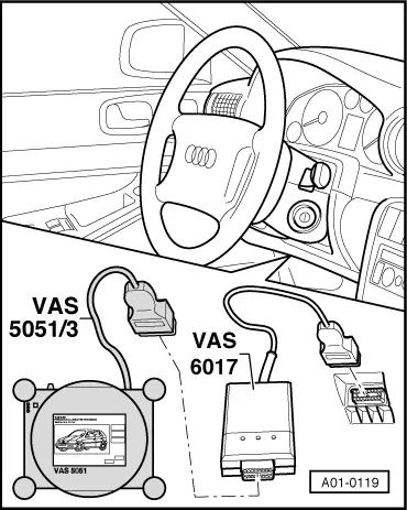
–  With the ignition switched off, connect up vehicle diagnostic, testing and information system -VAS 5051A- using, for example, diagnostic wire -VAS 5051/5A- and K-wire adapter -VAS 6017B- (or K-wire adapter -VAS 6017A-) to the 16-pin diagnostic socket in the vehicle → Chapter.
  Note
On vehicles as of chassis number “400000” in Model Year 2005 (Saloon and Avant; gradual introduction for the Cabrio in week 46/04 with no prior specification of any particular chassis number → Parts List) and depending on the vehicle equipment, certain control units will no longer be connected to the K / L-wire of the 16-pin diagnostic socket in the vehicle (e.g. engine control unit -J623-, automatic gearbox control unit -J217- and airbag control unit -J234-) → Current flow diagrams, Electrical fault finding and Fitting locations. These control units use “CAN signal wires” to exchange information for example with the vehicle diagnostic, testing and information system -VAS 5051A-. As the K-wire adapter -VAS 6017A- is not provided with these connections, the K-wire adapter -VAS 6017B- is required for the self-diagnosis of these control units.
–  Switch on ignition.
  A01-0119
–  Select “Vehicle self-diagnosis” function on vehicle diagnostic, testing and information system -VAS 5051A-.
  Note
t  Vehicle system selection prompt appears in display zone -1-.
t  “Scrolling” the screen display with the bar -2- permits display of vehicle systems (for all vehicle models and equipment levels) which are intended for self-diagnosis but are not currently visible on the screen.
  A87-0312
–  Select the following vehicle systems and read out fault memory of these systems:
–  17 - Dash panel insert
–  08 - Air conditioner/heater electronics
–  18 - Supplementary/auxiliary heater
–  Eliminate cause of any faults displayed in these vehicle systems and erase fault memory.
–  Switch off ignition.
  A87-0313
–  By removing bolts -C-, detach auxiliary heater tailpipe -A- from noise insulation -D- (does not apply to horizontally installed auxiliary heater, e.g. on vehicles with 4-cyl. TDI engine).
–  Remove noise insulation and front bumper (does not apply to horizontally installed auxiliary heater, e.g. on vehicles with 4-cyl. TDI engine) → Rep. Gr.63.
–  Move front end module to service position (does not apply to horizontally installed auxiliary heater, e.g. on vehicles with 4-cyl. TDI engine). → Rep. Gr.63
–  If applicable, remove charge air cooler (only applies to vehicles with vertically installed auxiliary heater and turbocharger, e.g. on vehicles with 6-cyl. TDI engine) → Rep. Gr.21.
–  Detach coolant expansion tank from vehicle (only applies to horizontally installed auxiliary heater, e.g. on vehicles with 4-cyl. TDI engine). → Rep. Gr.19
  A82-0351
–  Detach fuel pipe -A- from auxiliary heater.
–  Attach graduated beaker -B- in area of fuel pipe -A- (e.g. with wire) and guide fuel pipe into graduated beaker.
  Note
t  The illustration shows the layout for a vehicle on which the auxiliary heater is installed vertically in the area of the left headlight. For vehicles with 4-cyl. TDI engine (auxiliary heater installed horizontally in area beneath coolant expansion tank), the check is to be performed accordingly.
t  If necessary, use a hose -C- to extend the fuel pipe -A-.
  A82-0347

Complete filling of fuel pipe > < Test requirements