| –
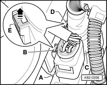
| Release connector -A- (coloured black at present) by pulling on tab -B-. |

Note | t
| Connector is released by pressing it towards control unit and pulling tab -E- whilst pressing connector. |
| t
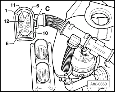
| The Fig. shows the position of the auxiliary heater control unit -J364- for an auxiliary heater fitted in a vehicle with 6-cyl. engine. |
| t
| For layout of components at or in auxiliary heater, refer to → Chapter |
| –
| Release connector -C- (coloured brown at present) by pulling on tab -D-. |
|
|
|