
A4 Cabriolet Mk2
 Note
Note
|

| Special tools and workshop equipment required |
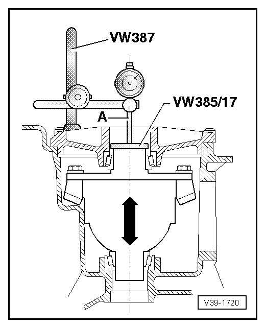
| t | End measuring plate -VW 385/17- |
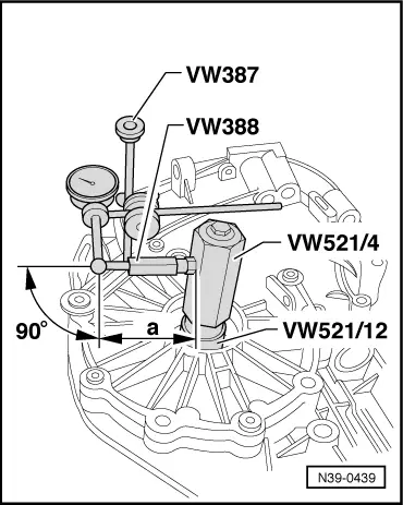
| t | Universal dial gauge bracket -VW 387- |
| t | Measuring lever -VW 388- |
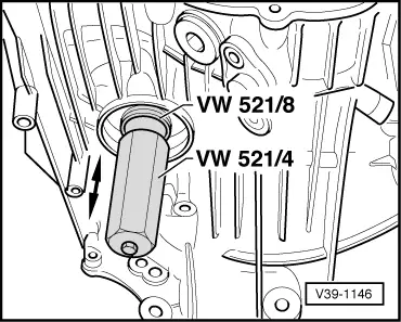
| t | Crown wheel adjusting tool -VW 521- |
| t | Retainer -3177- |
| t | Torque wrench -V.A.G 1331- |

| t | Dial gauge extension -VW 382/10- |
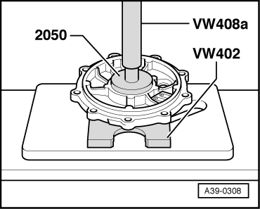
| t | Thrust plate -VW 402- |
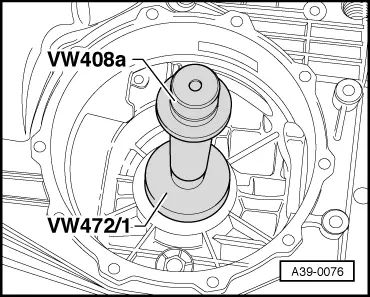
| t | Press tool -VW 408 A- |
| t | Removal and installing tool -VW 459/2- |
| t | Press tool -VW 472/1- |
| t | Extractor lever -VW 681- |
|
|
|
|
Note
|
|
|
|
Note |
|
|
|
| Example: | ||
| Inserted shim(s) “S2*” | 1.22 mm | |
| + | Measured value | 0.62 mm |
| + | Bearing preload (constant value) | 0.25 mm |
| = | Total shim thickness “Stotal” for “S1” plus “S2” | 2.09 mm |
Note
|
| Example: | ||
| Total shim thickness “Stotal” for “S1” + “S2” | 2.09 mm | |
| – | Inserted shim(s) “S2*” | 1.22 mm |
| = | Thickness of shim “S1*” | 0.87 mm |
|
|
|
| Distance “a” | Crown wheel Ø |
| 67 mm | 170 mm |
| 72 mm | 180 mm |
Note |
|
|
| Example: | ||
| 1st measured value | 0.28 mm | |
| + | 2nd measured value | 0.30 mm |
| + | 3rd measured value | 0.30 mm |
| + | 4th measured value | 0.28 mm |
| = | Sum of measured values | 1.16 mm |
| Example: | ||
| Inserted shim(s) “S2*” | 1.22 mm | |
| – | Average backlash | 0.29 mm |
| + | Lift (desired average value for backlash) | 0.15 mm |
| = | Thickness of shim “S2” | 1.08 mm |
|
| Available shims - Thickness of shims in mm 1)2) | ||||||
| 0.45 | 0.61 | 0.77 | ||||
| 0.49 | 0.65 | 0.81 | ||||
| 0.53 | 0.69 | 0.85 | ||||
| 0.57 | 0.73 | |||||
| ||||||
|
| Example: | ||
| Total shim thickness “Stotal” for “S1” plus “S2” | 2.09 mm | |
| – | Thickness of shim “S2” | 1.08 mm |
| = | Thickness of shim “S1” | 1.01 mm |
|
| Available shims - Thickness of shims in mm 1)2) | ||||||
| 0.45 | 0.61 | 0.77 | ||||
| 0.49 | 0.65 | 0.81 | ||||
| 0.53 | 0.69 | 0.85 | ||||
| 0.57 | 0.73 | |||||
| ||||||
Note
|
|