
A4 Cabriolet Mk2
| Renewing gearbox cover (with gearbox installed) |
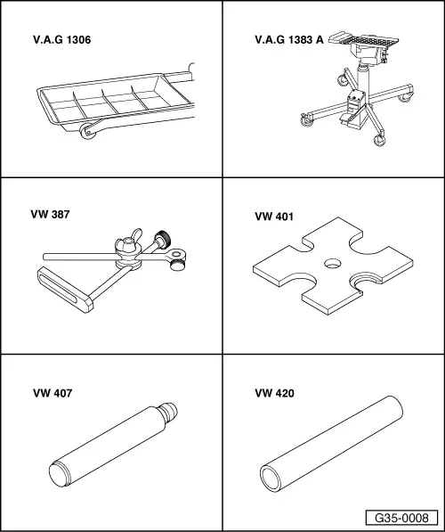
| Special tools and workshop equipment required |
| t | Drip tray -V.A.G 1306- or drip tray for workshop hoist-VAS 6208- |
| t | Engine and gearbox jack -V.A.G 1383 A- |
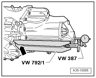
| t | Universal dial gauge bracket -VW 387- |
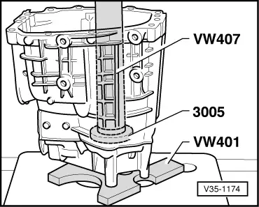
| t | Thrust plate -VW 401- |
| t | Press tool -VW 407- |
| t | Tube -VW 420- |

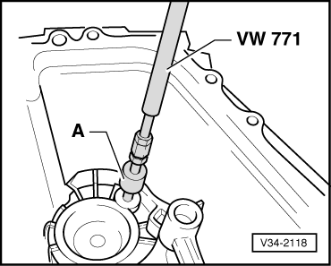
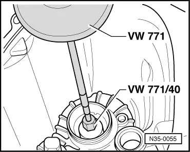
| t | Multi-purpose tool -VW 771- |
| t | Assembly device -VW 792- |
| t | Thrust plate -3005- |
| t | Multi-point bit -3357- |
| t | -1-Internal puller -Kukko 21/1- |
| t | Dial gauge |
| t | Dial gauge extension |
| t | Depth gauge (accurate to within 5/100 mm or less) |
| t | Sealants -AMV 188 001 02- |
|
 WARNING
 Note
Note
|
|
|
|
|
|
|
|
|
|
|
|
|
|
|
|
|
|
|
|
|
|
Note
|
|
Note
|
|
|
|
|
|
|
|
Note
|
|
|
|
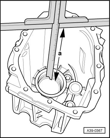
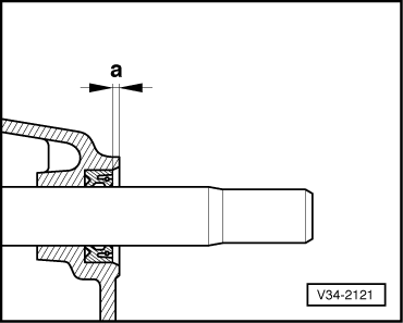
| Depth “a” (old gearbox cover) | 257.40 mm | |
| Depth “a” (new gearbox cover) | 257.56 mm | |
| = | Difference | 0.16 mm |
|
| Previous shim “S4” | 0.69 mm | |
| + | Difference | 0.16 mm |
| = | New shim “S4” | 0.85 mm |
|
|
|
Note
Note
|
|
Note
|
|
Note
|
|
|
|
|
|
|
|
|
|
|
|
Note
|
|
|
|
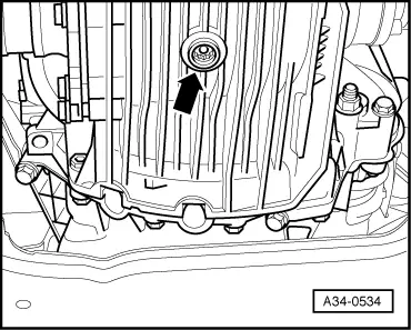
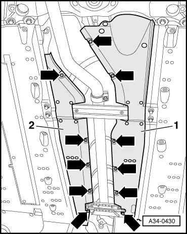
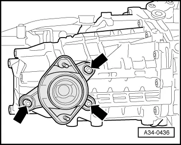
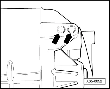
| Bolts -arrows- | 23 Nm |
|
|
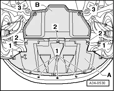
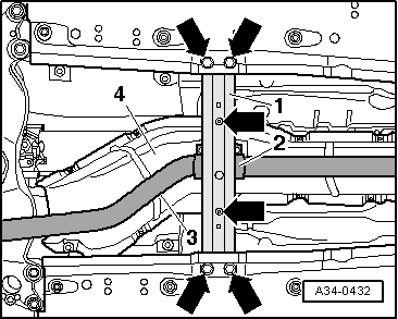
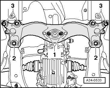
| Component | Nm | |||||
| -1- Tunnel cross member to gearbox mounting | 23 | |||||
| -2- Tunnel cross member to body 1) | 110 Nm + 90° 2) | |||||
| -3- Tunnel cross member to body 1) | M10 | 55 | ||||
| ||||||
| Component | Nm | |||
| Oil drain plug | 25 | |||
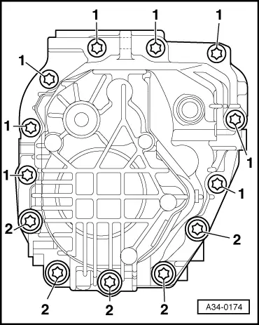
| Gearbox cover to gearbox housing | 22 | |||
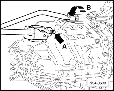
| Selector rod/selector joint to gearbox 1) | 23 | |||
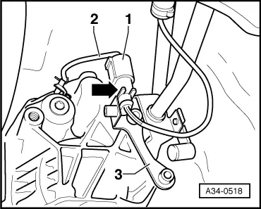
| Push rod to gearbox | 40 | |||
| Tunnel cross piece (front) to body | 55 | |||
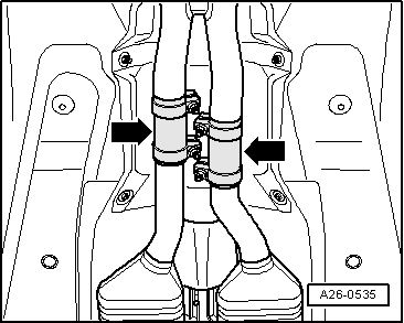
| Clamp for exhaust pipe | 40 | |||
| ||||