audi Workshop Repair Guides

Audi Workshop Service and Repair Manuals

Clutch, control > < Calculating transmission ratios "i”
General repair instructions
Proper tools and the maximum possible care and cleanliness are essential for satisfactory gearbox repairs. The usual basic safety precautions also naturally apply when carrying out repair work.
A number of generally applicable instructions for the various repair procedures - which were previously repeated at numerous places in the Workshop Manual - are summarised here. They apply to the work described in this Manual.
Special tools
For a complete list of special tools used in this Workshop Manual → Workshop equipment and special tools catalogue.
Gearbox
t  When installing a new gearbox, check the oil level and fill up with oil if necessary → Chapter.
t  Capacities and specifications → Chapter
t  When fitting a new rear final drive, check the oil level in the rear final drive and top up if necessary → Rep. Gr.39.
t  Thoroughly clean all joints and connections and the surrounding areas before dismantling.
t  When installing gearbox ensure dowel sleeves are correctly seated.
Sealants
t  Thoroughly clean joint surfaces on gearbox housing etc. before applying sealing paste.
t  Apply sealing paste -AMV 188 001 02- evenly and not too thickly.
t  Breather holes must remain free of sealing paste.
O-rings, oil seals and gaskets
t  Always renew O-rings, seals and gaskets.
t  After removing gaskets and seals, always inspect the contact surface on the housing or shaft for burrs resulting from removal or for other signs of damage.
t  Thoroughly clean housing joint surfaces before assembling.
   
t  Before installing oil seals, lightly oil the outer circumference of the seal and fill the space between the sealing lips -arrow- about half full with grease -G 052 128 A1-.
t  The open side of the oil seals faces toward the side with fluid filling.
t  When installing a new oil seal, position the seal in the housing so that the sealing lip does not contact the shaft in the same place as the old seal (make use of installation depth tolerances).
t  Lightly lubricate O-rings before installation to prevent them from being trapped and damaged during assembly.
t  Check oil level in gearbox after installing new seals and gaskets → Chapter.
  N32-0001
Locking elements
t  Do not over-stretch circlips.
t  Always renew circlips which have been damaged or over-stretched.
t  Circlips must be properly seated in the base of the groove.
t  Renew spring pins. Position: the slit -A- should be in line with the line of force -arrow-.
Nuts, bolts
t  Loosen the nuts and bolts in reverse sequence to the specified tightening sequence.
t  Nuts and bolts which secure covers and housings should be loosened and tightened in diagonal sequence and in stages if no tightening sequence is specified.
t  The tightening torques stated apply to non-oiled nuts and bolts.
t  Renew self-locking nuts and bolts.
t  Use a wire brush to clean the threads of bolts which are secured with locking fluid. Then apply locking fluid -AMV 185 101 A1- to bolt threads before installing.
t  Threaded holes which take self-locking bolts or bolts coated with locking fluid must be cleaned (using a tap or similar). Otherwise there is a danger of the bolts shearing off the next time they are removed.
Bearings
t  Install needle bearings so the lettering (side with thicker metal) faces towards the installing tool.
t  Mark the needle bearings of 1st to 5th speed selector gears when removing. This ensures the same installation position when re-installing.
t  Grease needle bearing for gearbox input shaft in flywheel.
t  Lubricate all bearings in gearbox housing with gear oil before installing.
t  Use inductive heater -VAS 6414- to heat inner races of tapered roller bearings to approx. 100°C before installing. Press home onto stop when installing so there is no axial clearance.
t  Do not interchange the outer or inner races of bearings of the same size (the bearings are paired).
t  Always renew the tapered roller bearings on one shaft together and use new bearings from a single manufacturer.
Shims
t  Use a micrometer to measure the shims at several points. Tolerance variations make it possible to obtain the exact shim thickness required.
t  Check for burrs and damage.
t  Do not install shims which are damaged or not in perfect condition.
Gears, synchronising hubs, inner rings for selector gears
t  Before installing, heat inner rings for selector gears to approx. 100° C using inductive heater -VAS 6414-.
t  Use inductive heater -VAS 6414- to heat gear wheels and synchronising hubs to approx. 100°C before installing. Press home onto stop when installing so there is no axial clearance.
t  Note correct installation position.
Selector gears
t  After installing, check that 1st to 5th speed selector gears and reverse selector gear have an axial clearance of 0.15 ... 0.35 mm and check that they rotate freely.
Synchro-rings
t  Do not interchange synchro-rings. When reusing always fit to the same selector gear.
t  Check for wear; renew if necessary.
t  Lubricate with gear oil when installing.
Checking synchro-rings with molybdenum coating
  A34-0149
t  The friction surface of an intact synchro-ring with molybdenum coating has a graphite-grey, slightly porous appearance. Clean the synchro-ring and make sure that the friction surface is free of oil.
t  The synchro-ring must be renewed if very shiny areas -A- have formed on the friction surface or if the brass-coloured metal underneath is already visible.
  A35-0049
Abnormal wear on selector gears and locking collars
t  Abnormal wear on synchro-ring or selector gear:
A - Worn dog teeth on synchro-ring or selector gear; ends of teeth completely worn away
  A35-0044
t  In comparison: intact synchro-ring or selector gear:
B - Intact dog teeth on synchro-ring or selector gear
  A35-0046
t  Abnormal wear on locking collar:
C - Worn internal splines on locking collar; ends of splines completely worn away
  A35-0047
t  
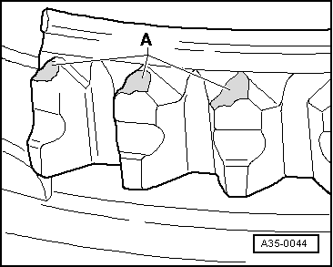
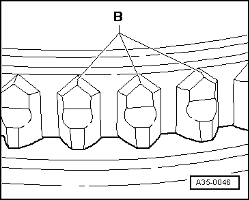
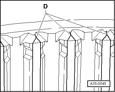
In comparison: intact locking collar:
D - Intact internal splines on locking collar
t  
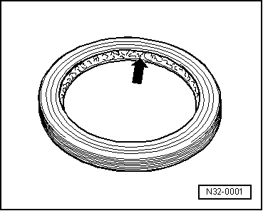
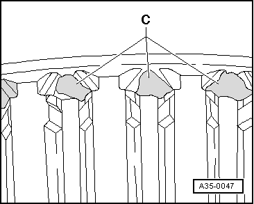
Always renew synchro-rings with carbon coating together with locking collar. Renew selector gears also if there are traces of wear.
Clutch actuation
t  When removing gearbox, remove clutch slave cylinder without disconnecting pipes.
t  Do not depress the clutch pedal after removing the clutch slave cylinder if the hydraulic pipe is still connected. Otherwise, the piston will be pressed out of the slave cylinder and be destroyed.
t  After installing the slave cylinder carefully press the clutch pedal. If you feel an unusually strong point of resistance when depressing the clutch pedal, you must not press it down further. The plunger of the slave cylinder is likely to have been guided past the clutch release lever. The slave cylinder would then be destroyed once pedal force exceeds approx. 300 N.
t  Ensure that the pressure plate is kept straight: loosen and tighten bolts consecutively in steps of 90° (1/4 turn each).
t  On vehicles with SAC pressure plate an adjuster ring has to be reset when only the clutch plate is renewed → Chapter.
t  Note assembly instructions for SAC pressure plate → Chapter.
t  Before renewing the master or slave cylinder on the assumption that it is defective you must first carry out a function check → Chapter.
t  If the clutch pedal does not return all the way to its initial position after releasing it (clutch pedal in rest position), you must bleed the clutch system (further measures → Chapter). The clutch system should be bled at the same intervals as the brake system → Booklet45.
t  If the clutch has burnt out, thoroughly clean the clutch housing, flywheel and parts of the engine facing the gearbox in order to prevent odour.
  A35-0045

Clutch, control > < Calculating transmission ratios "i”