audi Workshop Repair Guides

Audi Workshop Service and Repair Manuals

Adjusting pinion shaft > < Dismantling and assembling differential
Adjusting pinion shaft and crown wheel
General notes
t  Careful adjustment of the crown wheel and pinion shaft is essential to ensure that the final drive gives long service and runs silently. For this reason, the pinion shaft and crown wheel are matched together during manufacture, and checked to ensure a good mesh pattern and quiet running in both directions of rotation. The position of quietest running is found by moving the pinion shaft in an axial direction and at the same time lifting the crown wheel out of the zero-play mesh position by the amount necessary to maintain the backlash within the specified tolerance.
t  The deviation, or tolerance “r”, which is related to the master gauge “Ro”, is marked on the outer circumference of the crown wheel. Only renew gear set (crown wheel and pinion shaft) together!
   
Adjustment and marking of final drive gear set
1 - Identification “K831” denotes an Klingelnberg gear set with a ratio of 31 : 8.
2 - Gear set pairing number “312”.
3 - Deviation (tolerance) “r” is based on the master gauge used on the test machine in production. The dimension “r” is always given in 1/100 mm. For example: “25” indicates r = 0.25 mm
Ro - Length of master gauge used on test machine Ro = “59.65 mm”
R - Actual distance between centre axis of crown wheel and face of pinion shaft at point with quietest running for this gear set.
Vo - Hypoid offset

   
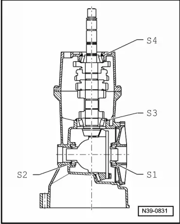
Shims; installation position
  Note
Table of adjustments when renewing individual components of gearbox → Anchor.
S1 - Shim for crown wheel in cover for final drive
S2 - Shim for crown wheel in gearbox housing
S3 - Adjustment shim for pinion shaft in gearbox housing
S4 - Adjustment shim for pinion shaft in bearing plate

Table of adjustments
  Note
If repairs have been carried out to the gearbox, it is only necessary to adjust the pinion shaft, crown wheel or final drive gear set if components have been renewed which have a direct effect on the adjustment of the final drive. Refer to the following table to avoid unnecessary adjustment work:
   
Components renewed:Components requiring adjustment:
 Crown wheel
“S1”+“S2”1) → Chapter
Pinion shaft
“S3”+“S4”1) via deviation “r” → Chapter
Pinion shaft
“S4”1) → Chapter
Checking backlash → Anchor
Gearbox housingXX X
Bearing plate  XX
Differential cageX  X
Tapered roller bearing for pinion shaft X X
Tapered roller bearings for differentialX  X
Final drive gear set 2)XX X
Cover for final driveX  X
t  1) Installation position of shims → Anchor.
t  2) Pinion shaft and crown wheel; only renew together.

   
Re-adjustment sequence for final drive gear set
The following work sequence is recommended to save time when the pinion shaft and crown wheel have to be adjusted:
1.  Determine total shim thickness “Stotal” for “S1” + “S2” to give specified preload for tapered roller bearings for differential.
2.  Determine total shim thickness “Stotal” for “S3”+ “S4” to give specified preload for pinion shaft tapered roller bearings.
3.  Distribute total shim thickness “Stotal” for “S3” + “S4” so that the distance from centre of crown wheel to face of pinion shaft is the same as distance “R” which was determined during production.
4.  Distribute total shim thickness “Stotal” for “S1” + “S2” so that the specified backlash between crown wheel and pinion shaft is maintained.
The object of the adjustment is to reproduce the setting for quietest possible running, as obtained on the test machine in production. For good results, maximum care and cleanliness are very important when performing repairs and taking measurements.
  N39-0831

Adjusting pinion shaft > < Dismantling and assembling differential