audi Workshop Repair Guides

Audi Workshop Service and Repair Manuals

Checking oil level in manual gearbox > < Removing gearbox on vehicles with V6 TDI engine
Installing gearbox
Installing gearbox
Procedure
Installation is carried out in reverse sequence; note the following:
  Note
t  Renew self-locking nuts and bolts.
t  Always renew seals/gaskets, oil seals and O-rings.
t  Re-attach all cable ties at the same locations when re-installing.
–  Clean input shaft splines and (in the case of used clutch plates) the hub splines. Remove corrosion and apply only a very thin coating of grease for clutch plate splines -G 000 100- to the splines. Do not grease guide sleeve.
l  It should be possible to push the clutch plate back and forth slightly on the input shaft.
–  Check whether dowel sleeves for aligning gearbox with engine are in the engine flange. Insert if necessary → Anchor.
–  Check clutch release bearing for wear and renew if necessary.
–  Checking and servicing release bearing with glued plastic ring → Fig.
–  Checking release bearing with mechanically attached plastic ring → Fig.
–  Check that dowel sleeves for centralising engine/gearbox are in the cylinder block, install if necessary.
–  Before installing gearbox, tie electrical wiring off to one side so that it cannot be trapped between the engine and the gearbox.
–  If fitted, place intermediate plate on dowel sleeves at engine flange.
   
Vehicles with V6 TDI engine:
–  Before installing gearbox, check that brace -B- is still moved to one side -direction of arrow-.
  A34-0116
Continued for all vehicles:
–  Lightly lubricate surface where operating rod and clutch release lever -arrow B- make contact with copper grease -Z 381 351 TE-.
–  Raise gearbox far enough to be able to install clutch slave cylinder with bracket for hose/pipe assembly.
–  Guide slave cylinder -1- into opening in gearbox housing keeping it as straight as possible (without tilting operating rod -arrow A-) and insert in recess -arrow B- on clutch release lever -3-.
  Note
If the slave cylinder -1- is inserted at an angle, there is a danger that the operating rod -arrow A- will be guided past the clutch release lever -3-.
–  Secure slave cylinder with new bolt -2-.
–  When aligning the gearbox with the engine, turn crankshaft back and forth slightly to make it easier to insert the gearbox input shaft splines into the clutch plate.
  Caution
t  After installing the slave cylinder press the clutch pedal carefully.
t  If you feel an unusually strong point of resistance when depressing the clutch pedal, you must not press it down further.
t  The operating rod of the slave cylinder is likely to have been guided past the clutch release lever.
t  The slave cylinder would then be destroyed once pedal force exceeds approx. 300 N.
t  For comparison: normal pedal force is approx. 115 N.
–  Install starter and tighten left and right engine/gearbox connecting bolts.
  A30-0162
–  Apply lifting column of engine and gearbox jack -V.A.G 1383 A- to gearbox from below (place a block of wood -1- between lifting column and gearbox).
–  Use engine and gearbox jack to lift gearbox up slightly.
  A34-0495
–  Tighten the 3 bottom engine/gearbox securing bolts -arrow-.
–  Lower gearbox slightly.
  A34-0433
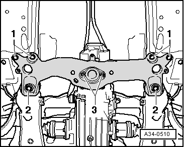
–  Bolt tunnel cross member onto gearbox mounting -3-.
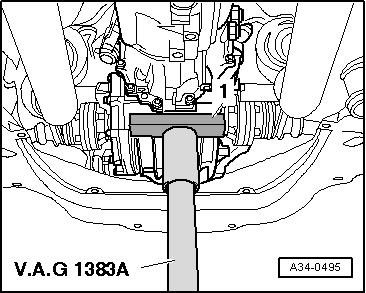
–  Raise gearbox using engine and gearbox jack -V.A.G 1383 A- and secure tunnel cross member to body using bolts -1- and -2- → Rep. Gr.40.
–  Bolt drive shafts to flange shafts → Rep. Gr.40.
–  Install exhaust system and align it so it is stress-free → Rep. Gr.26.
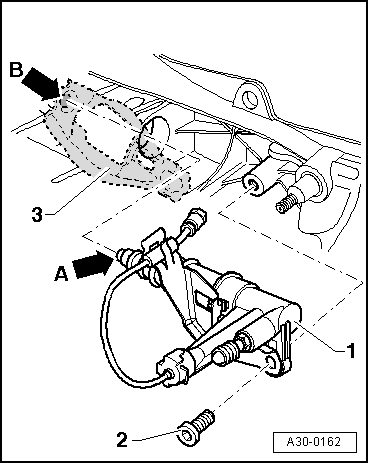
–  Check selector mechanism for correct adjustment, and re-adjust if necessary → Chapter.
–  If fitted, install tunnel brace → Rep. Gr.66.
–  Check oil level in manual gearbox → Chapter.
–  Follow the steps required after connecting the battery → Rep. Gr.27.
Tightening torques
  Note
t  Tightening torques apply only to lightly greased, oiled, phosphated or black-finished nuts and bolts.
t  Additional lubricant such as engine or gearbox oil may be used, but do not use graphite lubricant.
t  Do not use parts which have been degreased.
t  Tolerance for tightening torques ±15 %.
  A34-0510
Securing gearbox to engine on vehicles with 1.8 ltr. turbocharged engine:
  N34-1227
ItemBoltNm
1M12 x 6765
2M12 x 110 1)65
3M12 x 9065
4M10 x 50 2)45
5M10 x 4545
6M12 x 110 3)65
ADowel sleeves for centralising
l  1) With bracket for wiring
l  2) Special bolt with nut
l  3) With nut

   
Securing gearbox to engine on vehicles with 4-cyl. TDI engine:
  N34-1227
ItemBoltNm
1M12 x 7565
2M12 x 110 1)65
3M12 x 9065
4M10 x 50 2)45
5M10 x 4545
6M12 x 110 3)65
ADowel sleeves for centralising
l  1) With bracket for wiring
l  2) Special bolt with nut
l  3) With nut

   
Securing gearbox to engine on vehicles with V6 TDI engine:
  A34-0452
ItemBoltNm
1M12 x 80 1)65
2M12 x 90 2)65
3M12 x 8065
4M10 x 50 3)45
5M10 x 4545
6, 7M12 x 11065
8M12 x 6765
ADowel sleeves for centralising
l  1) With brace for turbocharger
l  2) With bracket for wiring
l  3) Special bolt with nut

All models:
   
ComponentNm
Slave cylinder to gearbox23 1)
Push rod to gearbox40
Selector rod to gearbox23
Connecting rod for selector rod to gearbox23
Engine speed sender -G28- to gearbox10
Gearbox mounting with bracket to gearbox23
Heat shield for drive shaft to gearbox23
Bracket for noise insulation to subframe10
l  1) Renew bolt.


Checking oil level in manual gearbox > < Removing gearbox on vehicles with V6 TDI engine