audi Workshop Repair Guides

Audi Workshop Service and Repair Manuals

Servicing clutch > < Checking release bearing
Removing and installing clutch slave cylinder
Special tools and workshop equipment required
   
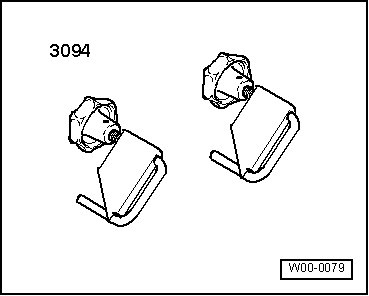
t  Hose clamps, up to Ø 25 mm -3094-
t  Lithium grease -G 052 150 A2-
t  Copper grease (commercially available)
Removing
Observe notes → Chapter „Notes on removing and installing clutch master cylinder and slave cylinder“.
  Note
Do not allow brake fluid to come into contact with the gearbox. If necessary, clean the gearbox housing.
  Caution
If slave cylinder is removed from gearbox with pipe/hose assembly still attached, make sure you do not press clutch pedal. Otherwise, the piston will be pressed out of the slave cylinder and be destroyed.
  W00-0079
Vehicles with V6 petrol engine:
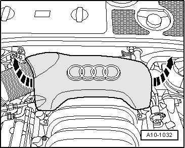
–  Pull off rear engine cover panel -arrows-.
  A10-1032
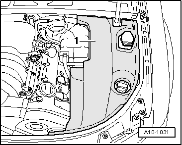
–  Remove cover -1- on left side of engine compartment.
  A10-1031
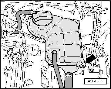
–  Unbolt coolant expansion tank -arrow-.
–  Unplug electrical wiring leading to coolant shortage indicator switch -F66- at expansion tank (bottom) and tie up expansion tank clear to one side (with coolant hoses -1 ... 3- attached).
  A10-0989
–  If fitted, remove heat shield for connectors from left of bulkhead.
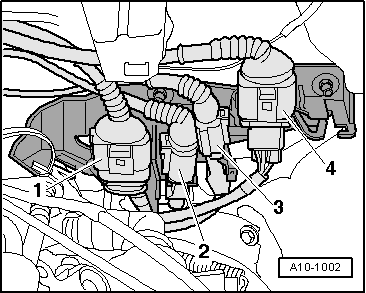
–  Detach electrical connectors -1 ... 4- from retainer on bulkhead (left-side).
–  Unplug electrical connectors -1- and -4-.
–  Move Lambda probe wires clear.
–  Remove retainer for connectors.
  A10-1002
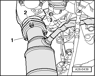
–  Unscrew nut -2- (accessible from above), connecting front exhaust pipe to exhaust manifold on left side.
  Note
t  For illustration purposes here shown with engine removed.
t  The nuts -1- and -3- (accessible from below) are removed at a later stage.
  A26-0439
Continued for all vehicles:
–  Remove front left wheel.
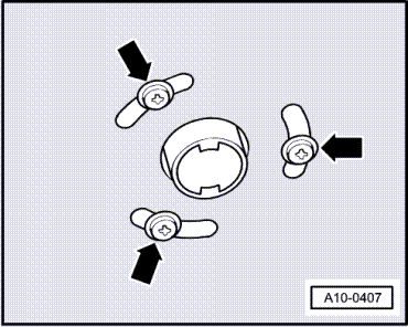
–  On vehicles fitted with auxiliary heater, remove bolts -arrows- securing exhaust pipe of auxiliary/ additional heater to noise insulation.
  A10-0407
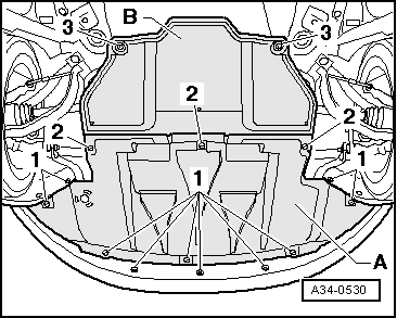
–  Release fasteners -1 ... 3- and detach noise insulation panels (front -A- and, if fitted, rear -B-).
  A34-0530
Vehicles with V6 petrol engine:
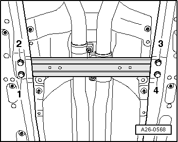
–  Unscrew bolts -1 ... 4- and remove front cross piece, if fitted.
  Note
  A26-0568
The flexible pipe connection (de-coupling element) on the front exhaust pipe must not be bent more than 10° – otherwise it can be damaged.
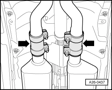
–  Disconnect exhaust system at clamp (left-side) -left arrow-.
  A26-0437
–  Unscrew nuts -1- and -3- (accessible from below) connecting front exhaust pipe to exhaust manifold on left side.
–  Detach front exhaust pipe from exhaust manifold on left side and remove front section of exhaust system.
Continued for all vehicles:
–  If necessary, unbolt drive shaft (left-side) from flange shaft and move clear to front, taking care not to damage protective coating.
  A26-0439
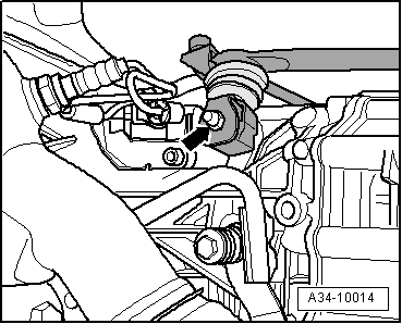
–  Unscrew nut -arrow- and detach gearbox selector lever from selector shaft.
  A34-10014
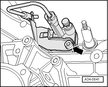
–  Remove bolt -arrow- and take out clutch slave cylinder from the rear.
  Note
Do not depress clutch pedal after removing clutch slave cylinder.
  A34-0641
–  Using hose clamp -3094-, clamp off pipe/hose assembly.
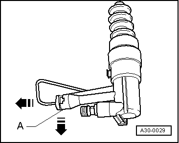
–  Release retaining clip -A- using a screwdriver and pull out to limit stop.
–  Detach pipe/hose assembly from clutch slave cylinder.
Installing
Installation is carried out in reverse sequence; note the following:
  Note
t  Renew securing bolt.
t  When installing, press in slave cylinder so that securing bolt can be fitted easily.
  A30-0029
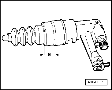
–  Before inserting slave cylinder in gearbox housing, lubricate area -a- of sleeve with lithium grease -G 052 150 A2-.
–  Lightly lubricate surface where plunger and clutch release lever make contact with copper grease (commercially available).
  A30-0037
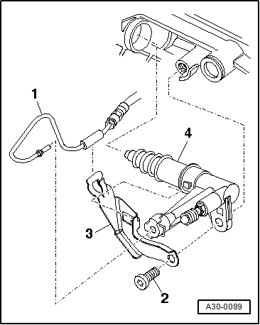
–  Attach bracket -3- for pipe/hose assembly to slave cylinder -4-.
  A30-0089
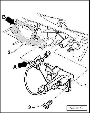
–  Guide slave cylinder -1- into opening in gearbox housing keeping it as straight as possible (without tilting plunger -arrow A-) and insert in recess -arrow B- on clutch release lever -3-.
  Note
If the slave cylinder -1- is inserted at an angle, there is a danger that the plunger -arrow A- will be guided past the clutch release lever -3-.
–  Secure slave cylinder with new bolt -2-.
  A30-0162
–  Press retaining clip -A- in clutch slave cylinder onto limit stop.
–  Push pipe/hose assembly onto connection on clutch slave cylinder so that retainer clip engages audibly.
–  Pull pipe/hose assembly to check that it is securely seated.
  Caution
t  After installing the slave cylinder press the clutch pedal carefully.
t  If you feel an unusually strong point of resistance when depressing the clutch pedal, you must not press it down further.
t  The plunger of the slave cylinder is likely to have been guided past the clutch release lever.
t  The slave cylinder would then be destroyed once pedal force exceeds approx. 300 N.
t  For comparison: normal pedal force is approx. 115 N.
  A30-0029
–  Install gearbox selector lever and tighten nut -arrow-.
–  If previously removed, attach drive shaft (left-side) to flange shaft → Rep. Gr.40.
Vehicles with 6-cylinder engine:
–  Install front exhaust pipe and perform stress-free alignment → Rep. Gr.26.
–  If fitted, install front cross piece → Rep. Gr.66.
–  Install heat shield for drive shaft (left-side).
Continued for all vehicles:
–  If the pipe-hose assembly was disconnected at the slave cylinder, the clutch system has to be bled after installing slave cylinder → Chapter.
Tightening torques
  A34-10014
ComponentNm
Slave cylinder to gearbox23 1)
Gearbox selector lever to selector shaft20 2)
Heat shield for drive shaft to gearbox23
l  1) Renew bolt
l  2) Renew nut


Servicing clutch > < Checking release bearing