
A4 Cabriolet Mk2
 Note
Note
|

| Special tools and workshop equipment required |
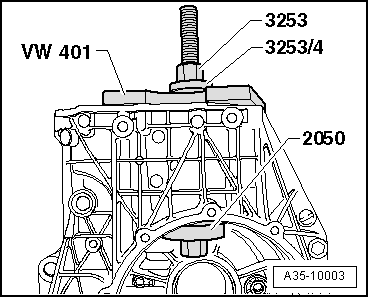
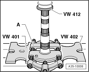
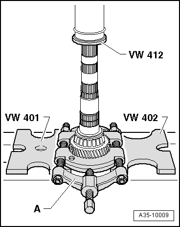
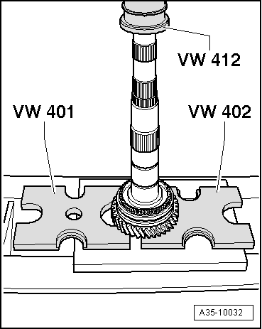
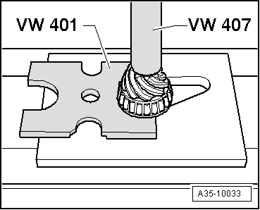
| t | Thrust plate -VW 401- |
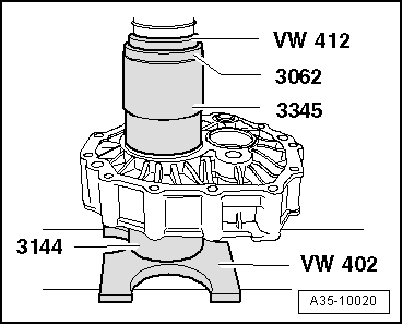
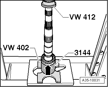
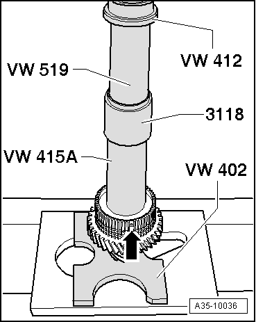
| t | Thrust plate -VW 402- |
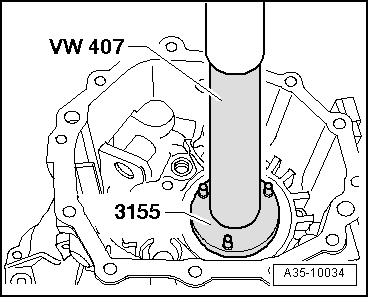
| t | Press tool -VW 407- |
| t | Press tool -VW 412- |
| t | Tube -VW 415 A- |
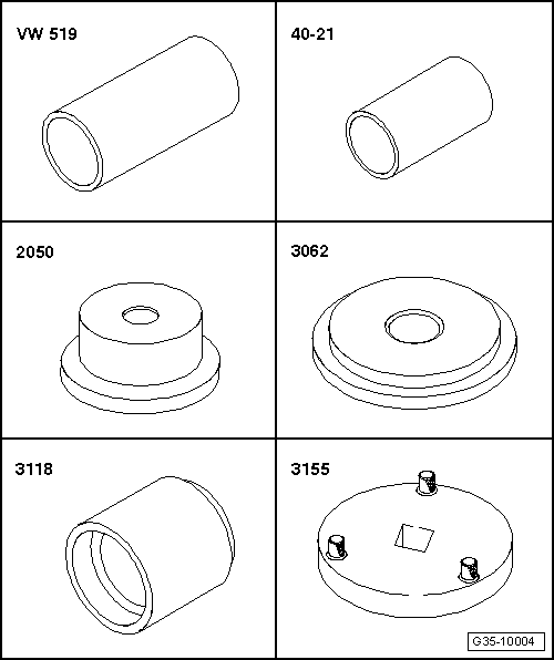
| t | Tube -VW 519- |
| t | Press tool -40 - 21- |
| t | Thrust piece -2050- |
| t | Thrust pad -3062- |
| t | Press tool -3118- |
| t | Slotted nut wrench -3155- |
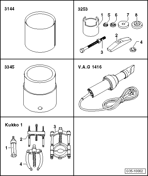
| t | Sleeve -3144- |
| t | Assembly tool -3253- |
| t | Wheel bearing tube -3345- |
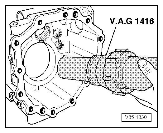
| t | Hot air blower -V.A.G 1416- |
| t | -1-Internal puller -Kukko 21/8- |
| t | -3-Splitter -Kukko 17/2- |
| t | -4-Counter-support -Kukko 22/2- |
|
|
|
|
|
|
|
|
|
|
|
|
|
|
|
|
 Caution
|
|
|
|
|
|
Note
|
|
|
|
| Circlip thickness (mm) | ||
| 2.50 | 2.56 | 2.62 |
| 2.53 | 2.59 | 2.65 |
|
| Circlip thickness (mm) | ||
| 1.90 | 2.02 | 2.14 |
| 1.93 | 2.05 | 2.17 |
| 1.96 | 2.08 | |
| 1.99 | 2.11 | |
|
| Circlip thickness (mm) | ||
| 3.50 |
|
| Circlip thickness (mm) | ||
| 3.50 |
|
| Circlip thickness (mm) | ||
| 1.90 | 1.98 | 2.06 |
| 1.94 | 2.02 | 2.10 |
|
| Circlip thickness (mm) | ||
| 1.90 | 2.02 | 2.14 |
| 1.93 | 2.05 | 2.17 |
| 1.96 | 2.08 | 2.20 |
| 1.99 | 2.11 | |
|
Note
|
|
|
|
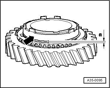
| Gap -a- | As-new installation value | Wear limit |
| Inner ring for 1st gear | 1.2 ... 2.0 mm | 0.6 mm |
|
|
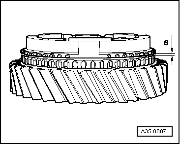
| Gap -a- | As-new installation value | Wear limit |
| 1st and 2nd gear | 1.4 ... 2.0 mm | 0.8 mm |
|
|
|
|
|
|
|
|
|
|
|
|