audi Workshop Repair Guides

Audi Workshop Service and Repair Manuals

Transporting gearbox > < Removing gearbox - vehicles with 2.7 ltr. TDI engine
Installing gearbox in vehicles with 2.7 ltr. TDI engine
Installation is carried out in reverse sequence; note the following:
–  Use a thread tap to remove any remaining locking fluid from all threaded holes which will accommodate self-locking bolts.
–  Always renew self-locking bolts and nuts.
–  Clean input shaft splines and (in the case of used clutch plates) the hub splines. Remove corrosion and apply only a very thin coating of grease for clutch plate splines -G 000 100- to the splines. Do not grease guide sleeve.
l  It should be possible to push the clutch plate back and forth slightly on the input shaft.
   
–  Check clutch release bearing for wear and renew if necessary → Item.
–  If plastic ring -arrows- has come loose, service release bearing as required → Fig..
  Note
The release bearing must be renewed if the groove worn on the plastic ring is deeper than 0.8 mm.
–  Check that dowel sleeves for centralising engine/gearbox are in the cylinder block, install if necessary.
–  If fitted, place intermediate plate on dowel sleeves at engine flange.
–  Before installing gearbox, tie electrical wires and brackets off to one side so that they are not trapped between the engine and the gearbox.
  N30-0285
–  Place gearbox on engine and gearbox jack.
–  Align adjustment plate and gearbox parallel to one another.
–  Attach support elements-arrows- on right side of gearbox.
  A34-0577
–  Secure support elements-arrow A- and -arrow B- to left side of gearbox.
  N34-10324
–  Lightly lubricate surface where plunger and clutch release lever make contact -arrow B- using copper grease (commercially available).
–  Raise gearbox far enough to be able to install clutch slave cylinder with bracket for pipe/hose assembly.
–  Guide slave cylinder -1- into opening in gearbox housing, keeping it as straight as possible (without tilting plunger -arrow A-) and insert in recess -arrow B- on clutch release lever -3-.
  Note
If the slave cylinder -1- is inserted at an angle, there is a danger that the plunger -arrow A- will be guided past the clutch release lever -3-.
  A30-0162
–  Secure clutch slave cylinder with new bolt -arrow-. Tightening torque → Item
  Caution
t  Press the clutch pedal carefully after installing the gearbox.
t  If you feel an unusually strong point of resistance when depressing the clutch pedal, you must not press it down further.
t  The plunger of the slave cylinder is likely to have been guided past the clutch release lever.
t  The slave cylinder would then be destroyed once pedal force exceeds approx. 300 N.
t  For comparison: normal pedal force is approx. 115 N.
–  When aligning the gearbox with the engine, turn crankshaft back and forth slightly to make inserting the gearbox input shaft splines into the clutch plate easier.
–  Bolt gearbox onto engine.
  A34-0641
–  Install gearbox selector lever and tighten nut -arrow-. Tightening torque → Item
  A34-10014
–  Install push rod -1-; to do so, tighten hexagon socket head bolt. Tightening torque → Item
–  Secure connecting rod -2- for selector rod. Tightening torque → Item
  N34-1208
–  Tighten bolts -1 … 3- for tunnel cross member → Chapter.
  A34-0510
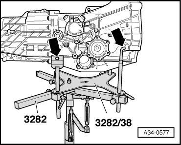
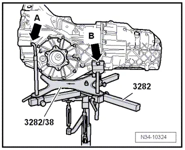
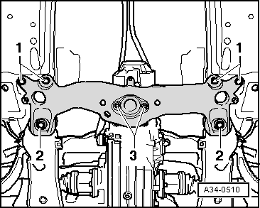
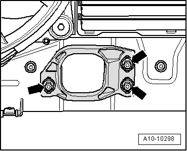
–  Loosen bolts -arrows- for torque reaction support.
–  Allow stop for torque reaction support to settle on rubber buffer for torque reaction support under its own weight and re-tighten bolts.
The remaining installation steps are carried out in the reverse sequence; note the following points:
–  Bolt drive shafts to flange shafts → Running gear, front-wheel drive and four-wheel drive; Rep. gr.40.
–  Install front exhaust pipe with particulate filter → Engine, mechanics; Rep. gr.26.
–  Follow steps required after connecting battery → Electrical system; Rep. gr.27.
  Caution
Never use a charger to aid starting. Otherwise, the vehicle's control units could be damaged.
Tightening torques
  Note
t  Tightening torques apply only to lightly greased, oiled, phosphated or black-finished nuts and bolts.
t  Additional lubricant such as engine or gear oil may be used, but do not use graphite lubricant.
t  Do not use parts which have been degreased.
t  Tolerance for tightening torques is ± 15%.
  A10-10298
Gearbox to engine
  A10-10069
ItemBoltNm
1, 2M10 x 12565 1)
3, 4, 5M12 x 10565
6, 7M12 x 12065
8, 9, 10M10 x 8045
ADowel sleeves for centralising
1) Property class 10.9.

   
ComponentNm
Heat shield for drive shaft to gearbox23
Engine mounting to engine support23
Bracket for noise insulation to subframe10
Stop for torque reaction support28


Transporting gearbox > < Removing gearbox - vehicles with 2.7 ltr. TDI engine