
A4 Cabriolet Mk2
 Note
Note
|

| Special tools and workshop equipment required |
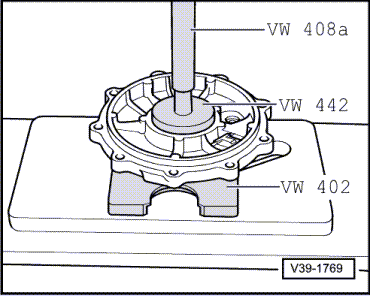
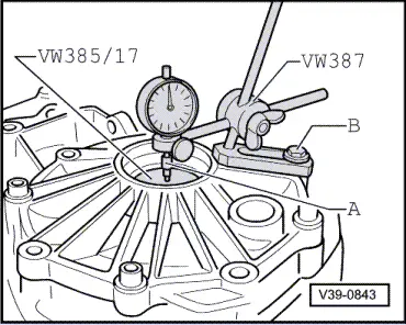
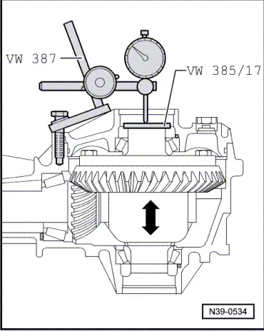
| t | End measuring plate -VW 385/17- |
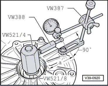
| t | Universal dial gauge bracket -VW 387- |
| t | Measuring lever -VW 388- |
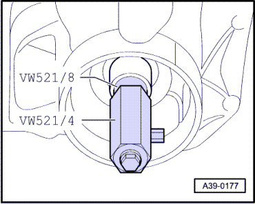
| t | Crown wheel adjusting tool -VW 521- |
| t | Torque wrench -V.A.G 1331- |
| t | Dial gauge |
| t | Hexagon bolt M 8 x 45 |
Note
|
|
|
|
|
|
|
|
|
| Example: | ||
| Inserted shim “S2*” | 1.00 mm | |
| + | Measured value | 0.50 mm |
| + | Bearing preload (constant value) | 0.30 mm |
| = | Total shim thickness “Stotal” for “S1” plus “S2” | 1.80 mm |
Note
|
| Example: | ||
| Total shim thickness “Stotal” for “S1” + “S2” | 1.80 mm | |
| – | Inserted shim(s) “S2*” | 1.00 mm |
| = | Thickness of shim “S1*” | 0.80 mm |
|
| Example: | ||
| 1st measured value | 0.28 mm | |
| + | 2nd measured value | 0.30 mm |
| + | 3rd measured value | 0.30 mm |
| + | 4th measured value | 0.28 mm |
| = | Sum of measured values | 1.16 mm |
Note
|
| Example: | ||
| Inserted shim(s) “S2*” | 1.00 mm | |
| – | Average backlash | 0.29 mm |
| + | Lift (desired average value for backlash) | 0.15 mm |
| = | Thickness of shim “S2” | 0.86 mm |
|
| Example: | ||
| Total shim thickness “Stotal” for “S1” plus “S2” | 1.80 mm | |
| – | Thickness of shim “S2” | 0.86 mm |
| = | Thickness of shim “S1” | 0.94 mm |
|
Note
|
|