
A4 Cabriolet Mk2
| Removing and installing gearbox cover and selector shaft - exploded view |
 Note
Note| t | Removing and installing 1st, 2nd and reverse gear → Chapter |
| t | Removing and installing input shaft, pinion shaft, hollow shaft and selector rods → Chapter. |
| t | Do not interchange locking bushes for selector shaft and selector rods. Apply marking prior to removal. |
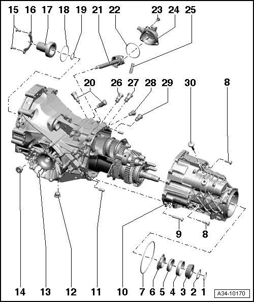
| 1 - | Circlip |
| q | Note thickness |
| q | Re-determining thickness → Anchor |
| 2 - | Washer |
| q | Note thickness |
| q | Re-determining thickness → Anchor |
| 3 - | Tapered roller bearing inner race |
| q | Can be removed and installed by hand |
| 4 - | Tapered roller bearing outer race |
| q | Can be removed and installed by hand |
| 5 - | Spacer ring |
| q | Secures 12-point nut → Item on hollow shaft to prevent it from working loose |
| 6 - | 12-point nut, 75 Nm |
| 7 - | O-ring |
| q | Always renew |
| q | Lubricate with gear oil |
| q | Insert in circumferential groove in gearbox cover |
| 8 - | Bolt, 27 Nm |
| q | 2 x |
| q | Self-locking |
| q | Renew |
| 9 - | Bolt, 24 Nm |
| q | 13 x |
| 10 - | Gearbox cover |
| q | Servicing → Chapter |
| 11 - | Dowel pin |
| q | 2 x |
| q | Insert in gearbox cover |
| 12 - | Oil drain plug, 40 Nm |
| 13 - | Gearbox housing |
| q | Removing and installing differential → Chapter |
| q | Servicing gearbox housing → Chapter |
| 14 - | Oil filler plug, 40 Nm |
| 15 - | Bolt, 24 Nm |
| q | 2 x |
| q | Apply locking fluid -AMV 185 101 A1- when fitting |
| 16 - | Retaining piece |
| q | For guide sleeve |
| 17 - | Guide sleeve |
| q | With oil seal |
| q | Removing and installing oil seal → Item |
| 18 - | O-ring |
| q | Always renew |
| q | Lubricate with gear oil |
| q | Insert in circumferential groove in gearbox cover |
| 19 - | Circlip |
| q | Insert in circumferential groove in input shaft |
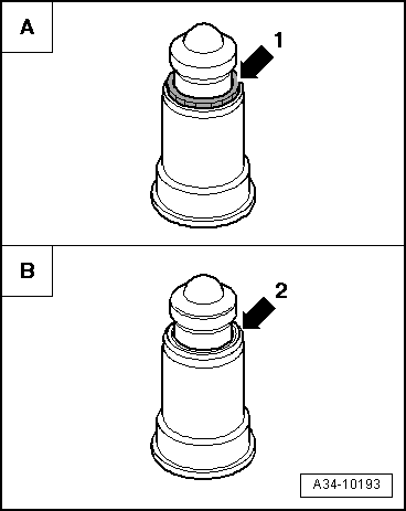
| 20 - | Locking bush |
| q | For selector shaft |
| q | 2 x |
| q | Do not interchange locking bushes for selector shaft and selector rods |
| q | Modification: with flanged edge on ball sleeve → Fig. |
| 21 - | Selector shaft with selector cylinder |
| q | Removing and installing → Chapter |
| 22 - | O-ring |
| q | For selector shaft cover |
| q | Always renew |
| q | Lubricate with gear oil |
| q | Insert in circumferential groove in selector shaft cover |
| 23 - | Bolt, 24 Nm |
| q | 3 x |
| q | Apply locking fluid -AMV 185 101 A1- when fitting |
| 24 - | Cover for selector shaft |
| q | With reversing light switch -F4- |
| q | Removing and installing reversing light switch -F4- → 6-speed manual gearbox 0A3, four-wheel drive; Rep. Gr.34 |
| q | Tightening torque for reversing light switch -F4-, 20 Nm |
| 25 - | Pin |
| q | For selector shaft stop |
| q | Insert in drilling in gearbox housing. |
Note| t | There are two versions of pins: with or without a lug. Please refer to → Electronic parts catalogue “ETKA” for correct version. |
| t | Installation position of pin with lug: insert end with lug into gearbox housing. |
| 26 - | Locking bush |
| q | For 5th and 6th gear selector rod |
| 27 - | Locking bush |
| q | For 3rd and 4th gear selector rod |
| 28 - | Locking bush |
| q | For 1st and 2nd gear selector rod |
| 29 - | Locking bush |
| q | For reverse gear selector rod |
| 30 - | Bolt, 24 Nm |
Note
|
|