
A4 Cabriolet Mk2
| Servicing gearbox cover |
| Special tools and workshop equipment required |
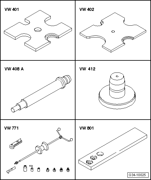
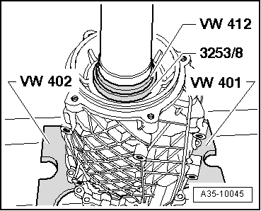
| t | Thrust plate -VW 401- |
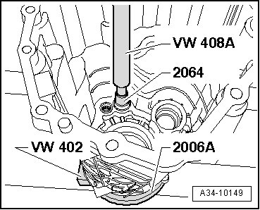
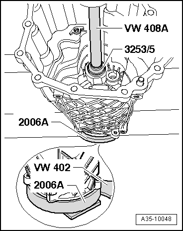
| t | Thrust plate -VW 402- |
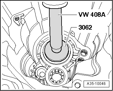
| t | Press tool -VW 408 A- |
| t | Press tool -VW 412- |
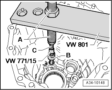
| t | Multi-purpose tool -VW 771- |
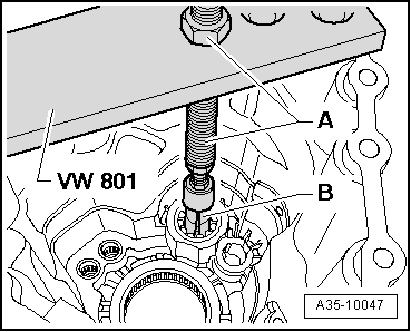
| t | Support plate -VW 801- |

| t | Thrust ring -2006 A- |
| t | Locking pin -2064- |
| t | Thrust pad -3062- |
| t | Assembly tool -3253- |
| t | -1-Internal puller -Kukko 21/2- |
| t | -1-Internal puller -Kukko 21/4- |
| t | -4-Counter-support -Kukko 22/2- |
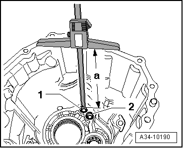
| t | Depth gauge |
| t | Stud M10 |

| 1 - | Gearbox cover |
| 2 - | Dowel pin |
| q | 2 x |
| q | Insert in gearbox cover |
| q | Drive in until flush with rear surface of housing flange |
| 3 - | Needle bearing |
| q | Bearing for hollow shaft in gearbox cover |
| q | Pressing out → Fig. |
| q | Pressing in → Fig. |
| q | Peen to secure after installing → Fig. |
| 4 - | Ball sleeve |
| q | For reverse gear selector rod |
| q | Pulling out → Fig. |
| q | Pressing in → Fig. |
| q | Measuring installation depth → Fig. |
| 5 - | Ball sleeve |
| q | For selector rod for 1st and 2nd gear |
| q | Pulling out → Fig. |
| q | Pressing in → Fig. |
| q | Measuring installation depth → Fig. |
| 6 - | Roller bearing |
| q | Bearing for input shaft in gearbox cover |
| q | Always renew |
| q | Pulling out → Fig. |
| q | Pressing in → Fig. |
| q | Peen to secure after installing → Fig. |
|
|
|
|
|
|
|
|
 Note
Note
|
|
|
|
|
|