
A4 Cabriolet Mk2
|
|
|
|
|
|
|
|
|
|
|
 Caution
 Note
Note
|
|
|
|
Note
|
|
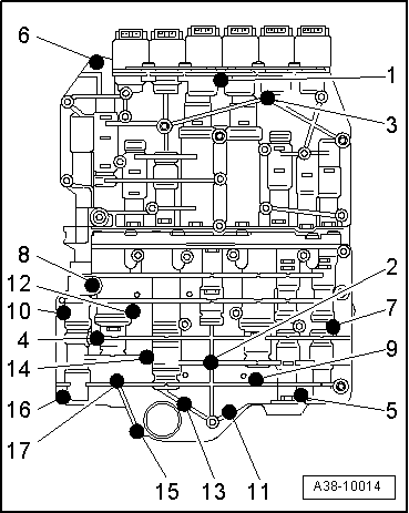
| Step | Tightening sequence | ||
| I |
| ||
| II |
|
|
|
|
|
|
|
|
|
|
|
| Component | Nm |
| Valve body to gearbox housing | 8 |