
A4 Cabriolet Mk2
| Crankshaft - exploded view of components |

| 1 - | Bearing shell |
| q | For cylinder block (with oil groove) |
| q | Do not interchange used bearing shells (mark positions) |
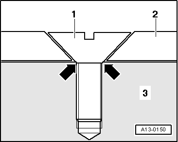
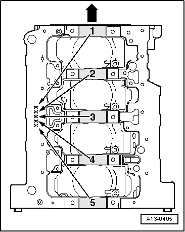
| q | Inserting bearing shells for cylinder block with correct colour-coding → Fig. |
| 2 - | Chain sprocket |
| q | For oil pump chain |
| q | Renewing → Chapter |
| 3 - | Bearing shell |
| q | For bearing cap (without oil groove) |
| q | Do not interchange used bearing shells (mark positions) |
| q | Inserting bearing shells for bearing cap with correct colour-coding → Fig. |
| 4 - | Thrust washers |
| q | For bearing No. 3 |
| q | Note location |
| 5 - | 65 Nm + 90° (1/4 turn) further |
| q | Renew |
| q | For measuring radial clearance of crankshaft, tighten to 65 Nm but not further |
| 6 - | Bearing cap |
| q | Bearing cap 1: Pulley end |
| q | Bearing cap 3 with recesses for thrust washers |
| q | Bearing shell retaining lugs (cylinder block/bearing cap) must be on the same side |
| 7 - | 10 Nm + 90° (1/4 turn) further |
| q | Renew |
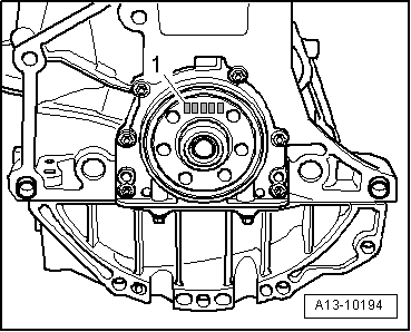
| q | Sender wheel must be renewed if bolts are loosened → Fig. |
| 8 - | Needle bearing |
| q | For vehicles with manual gearbox |
| q | Extracting and driving in: open version → Chapter, closed version → Chapter |
| 9 - | Sender wheel |
| q | For engine speed sender -G28- |
| q | Can only be installed in one position. Holes are off-set |
| q | Sender wheel must be renewed if bolts are loosened |
| q | Removing and installing → Fig. |
| 10 - | Crankshaft |
| q | Axial clearance (new): 0.07 ... 0.23 mm |
| q | Axial clearance: wear limit: 0.30 mm |
| q | Check radial clearance with Plastigage |
| q | Radial clearance (new): 0.02 ... 0.04 mm |
| q | Radial clearance: wear limit: 0.15 mm |
| q | Do not rotate the crankshaft when checking the radial clearance |
| q | Crankshaft dimensions → Chapter |
| Component | Nm | ||||
| Sender wheel to crankshaft | 10 + 90° 1)2) | ||||
| |||||
 Note
Note
|
|
| Letter on cylinder block | Colour coding of bearing | |
| B | = | Blue |
| R | = | Red |
| G | = | Yellow |
| S | = | Black |
| W | = | White |
|
|
| Letter on crankshaft | Colour coding of bearing | |
| B | = | Blue |
| R | = | Red |
| G | = | Yellow |
| W | = | White |