audi Workshop Repair Guides

Audi Workshop Service and Repair Manuals

Removing and installing balance shaft assembly with oil pump > < Part II: Balance shaft assembly with oil pump - exploded view
Removing and installing sump
   
Removing and installing sump
Special tools and workshop equipment required
t  Support bracket -10-222 A-
t  Allen key, long reach -T10058-
t  Used oil collection and extraction unit -V.A.G 1782-
t  Workshop hoist -VAS 6100-
t  Mud wing compensation plate -T40045-
t  Electric drill with plastic brush attachment
t  Safety goggles
t  Sealant → Parts catalogue

Removing
  Note
All cable ties which are released or cut open when removing must be fitted in the same position when installing.
   
–  Pull off engine cover panel -arrows-.
  A10-10292
–  Remove the rubber sealing strip from the edges of the wing mounting flanges.
–  Place compensation plates -T40045- between the wing mounting flange and the body flange underneath, so that the support bracket -10-222 A- does not damage the edges of the wings.
  A19-0412
–  Set up support bracket -10-222 A- with adapters -10-222/3- on wing panel flanges.
–  Attach spindles to the engine lifting eyes as illustrated.
–  Use spindles to slightly take up weight of engine.
–  Remove poly V-belt → Chapter.
  A17-10071
–  Vehicles with auxiliary heater: remove bolts -arrows- securing exhaust pipe for auxiliary/additional heater to noise insulation.
  A10-0407
–  Release quick-release fasteners -1- and -2- and take off front noise insulation.
–  If fitted, open quick-release fasteners -3- and remove rear noise insulation.
–  Place used oil collection and extraction unit -V.A.G 1782- under engine and drain engine oil.
  A10-1320
–  Unscrew bolts -arrows- and remove torque reaction support from sump.
–  Unscrew oil return pipe -1- from turbocharger at sump.
  A17-10119
–  Unplug electrical connector -arrow- at oil level and oil temperature sender -G266-.
  A17-0215
–  Unbolt refrigerant pipe bracket from sump -arrow-.
  A10-10286
–  Unplug electrical connector -1- for magnetic clutch on air conditioner compressor.
  Caution
The air conditioner refrigerant circuit must not be opened.
–  Unscrew air conditioner compressor from bracket -arrows-.
  Note
To prevent damage to the condenser and refrigerant pipes/hoses, ensure that the pipes and hoses are not stretched, kinked or bent.
–  Tie up air conditioner compressor to bottom of vehicle, with lines attached.
  A10-10234
–  Unplug electrical connector -arrow- at front left vehicle level sender -G78-.
  A40-0460
–  Unbolt anti-roll bar mountings -1- and -2-.
  A21-0251
–  Support subframe using workshop hoist -VAS 6100- or -V.A.G 1202 A-.
  A17-0037
–  Cut open the cable ties -arrows-, open bracket for starter wire and take out the electrical wire.
  A17-0045
–  Unscrew nut -3- at bottom of engine mounting.
–  Unscrew bolts -4- and -5- on console for engine mounting.
–  Unscrew bolt -1- (front) for subframe and remove console for engine mounting -2-.
–  Repeat procedure on other side of vehicle.
  A21-0252
–  Carefully lower subframe using workshop hoist -VAS 6100- or -V.A.G 1202 A-.
–  Lift engine up slightly using spindles of support bracket -10-222 A-; make sure the selector linkage and exhaust system do not become trapped.
  A17-0037
–  Unscrew gearbox/sump bolts -arrows-.
  A17-10067
–  Unscrew M10 bolts -arrows-.
–  Slacken bolts -1 ... 18- in diagonal sequence.
–  Take off sump; if necessary loosen it by striking lightly with a rubber hammer.
Installing
Installation is carried out in the reverse order; note the following:
l  Tightening torques → Chapter „Part I: Sump, balance shaft assembly - exploded view“
  Note
t  Renew seal.
t  Secure all hose connections with the correct type of hose clips (same as original equipment) → Parts catalogue.
t  Fit all cable ties in the original positions when installing.
  A17-0208
–  Remove sealant residue from sump and cylinder block with rotating plastic brush or similar.
  WARNING
Wear safety goggles.
–  Clean sealing surfaces; they must be free of oil and grease.
  Note
t  Sealant bead must not be wider than 3 mm, otherwise excess sealant could ingress into sump and clog strainer in oil intake pipe.
t  Take particular care when applying sealant bead in area of rear sealing flange -arrows-.
t  The sump must be installed within 5 minutes after applying sealant.
  N17-0012
–  Cut off tube nozzle at front marking (nozzle approx. 2 mm Ø).
  A17-0081
–  Apply bead of sealant onto the clean sealing surface of the sump as shown in the illustration.
l  Thickness of sealant bead: 2 ... 3 mm
  Note
  A17-0041
t  
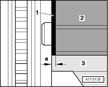
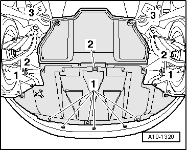
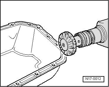
When installing the sump -3- with the engine removed from the vehicle, make sure that it is positioned flush with the intermediate plate -1- at the flywheel end. In other words, the sump should protrude by 0.8 mm (distance -a-) from cylinder block -2-.
t  After fitting sump assembly, the sealant must dry for approx. 30 minutes. Then (and only then) fill the engine with engine oil.
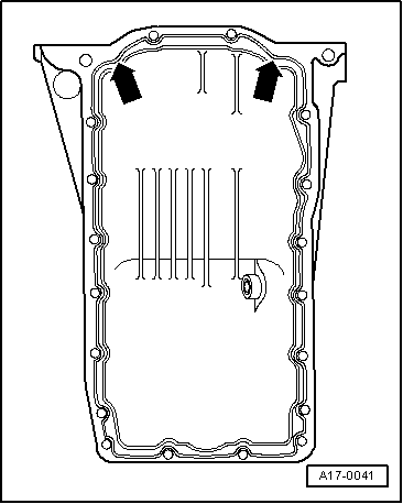
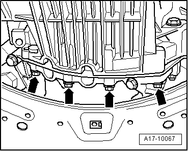
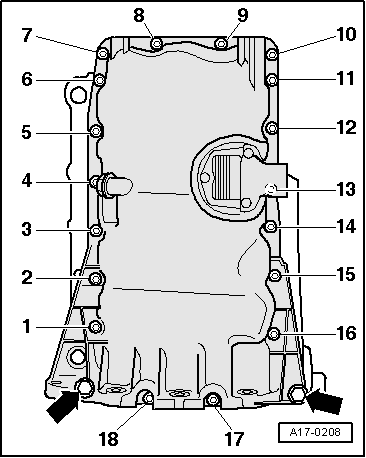
–  Immediately fit sump and tighten bolts; tightening sequence → Fig..
–  Install subframe → Running gear, front-wheel drive and four-wheel drive; Rep. Gr.40.
–  Install anti-roll bar → Running gear, front-wheel drive and four-wheel drive; Rep. Gr.40.
–  Install air conditioner compressor → Rep. Gr.87.
–  Install poly V-belt → Chapter.
–  Fill up with engine oil and check oil level.
Further assembly is basically carried out in reverse order of dismantling.
  A17-0128

Removing and installing balance shaft assembly with oil pump > < Part II: Balance shaft assembly with oil pump - exploded view