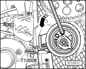
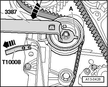
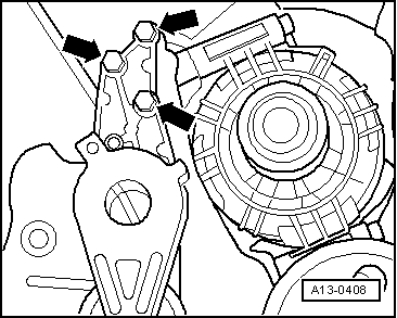
| Do not to bend limit stop -A- of eccentric adjuster. |
| –
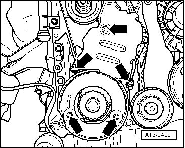
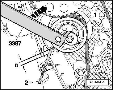
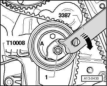
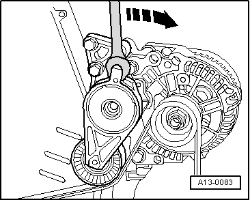
| To slacken toothed belt, loosen nut -1- on tensioning roller and turn eccentric adjuster clockwise -arrow- using pin wrench -3387-. |
| –
| Mark direction of rotation of toothed belt with chalk or felt pen. |
| Installing (adjusting valve timing) |

Note | t
| The toothed belt adjustment must also be performed as described below, even if the toothed belt has only been removed from the camshaft sprocket. |
| t
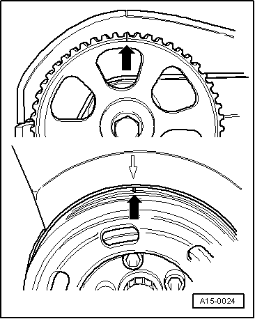
| The crankshaft must not be at TDC at any cylinder when the camshaft is turned. Otherwise, there is a risk of damage to valves and piston crowns. |
| –
| Fit toothed belt on crankshaft sprocket (note rotation direction). |
| –
| Install bottom toothed belt cover. |
Note |
|
|


 Caution