audi Workshop Repair Guides

Audi Workshop Service and Repair Manuals

Effects of leaks > < Connection diagram for charge pressure control and vacuum control - vehicles from 07.02 onwards
Checking turbocharger and charge pressure regulating valve
Special tools and workshop equipment required
   
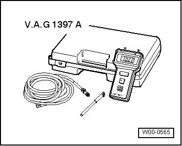
t  Turbocharger tester -V.A.G 1397 A-
  W00-0565
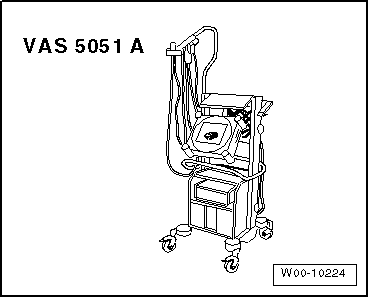
t  Vehicle diagnostic, testing and information system -VAS 5051 A-
Test conditions
l  All hoses and pipes securely fitted and and free of leaks.
l  Fault memory interrogated, final control diagnosis performed → Vehicle diagnostic, testing and information system VAS 5051.
Test sequence
  WARNING
t  Test equipment must always be secured on the rear seat and operated from that position by a second person.
t  If test and measuring instruments are operated from front passenger's seat and the vehicle is involved in an accident, the person sitting in this seat could be seriously injured when the airbag is triggered.
  W00-10224
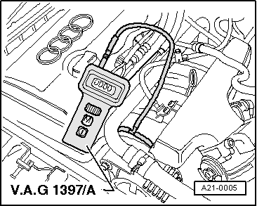
–  Connect T-piece with test hose of turbocharger tester -V.A.G 1397 A- to intake manifold (front).
–  Route test hose under rear edge of bonnet and through right window into passenger compartment.
  A21-0005
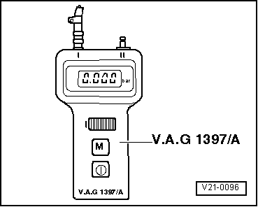
–  Switch on turbocharger tester and set measuring range selector switch to position -I- (absolute pressure).
–  Attach test hose to connection -I-.
  Note
t  Ensure absolute leakproof connection of hoses to avoid measurement errors.
t  Take care not to trap test hose at bonnet and side window.
t  Pressing memory button „M“ on turbocharger tester causes last measured value to be stored until memory button „M“ is pressed again or tester is switched off.
t  The decimal point in the display flashes to indicate that the value is being stored.
t  If the battery voltage of the turbocharger tester drops below the minimum level, an arrow will appear at the top left of the display.
t  Before performing the test, drive vehicle moderately fast for at least 3 km (without stopping at traffic lights etc.).
t  A second mechanic is required to note the readings on the tester when the vehicle is moving.
  V21-0096
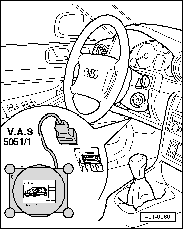
–  Connect vehicle diagnostic, testing and information system -VAS 5051 A- to diagnosis connector with ignition switched off.
–  Start engine.
  A01-0060
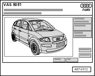
Display on -VAS 5051 A-:
–  Press the „Vehicle self-diagnosis“ key.
  A87-0312
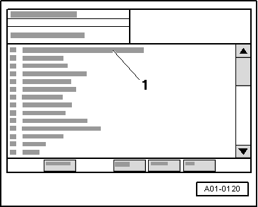
Display on -VAS 5051 A-:
–  From list -1- select vehicle system „01 Engine electronics“.
–  Wait until next display appears on tester.
  A01-0120
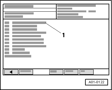
Display on -VAS 5051 A-:
–  From list -1- select diagnostic function „08 - Read measured value block“.
  A01-0122
Display on -VAS 5051 A-:
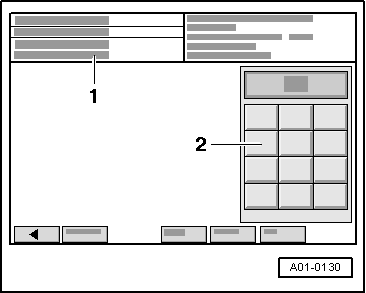
1 - Enter display group (highest possible entry = 255)
–  Use keypad -2- to enter „Display group number 115“ and confirm by touching the Q key.
–  Perform test drive.
–  Accelerate vehicle in 3rd gear from 2000 rpm at full throttle and observe rev counter.
–  Press PRINT key on -VAS 5051 A- and memory key -M- on -V.A.G 1397 A- simultaneously at approx. 2500 rpm.
  Note
The charge pressure should be measured using turbocharger tester -V.A.G 1397 A-. Vehicle diagnostic, testing and information system -VAS 5051 A- is used to check whether the charge pressure is being registered by the control unit.
  A01-0130
Display on -V.A.G 1397 A-:
l  Specification: 1.500 ... 1.600 bar.
  V21-0096
Display on -VAS 5051 A-:
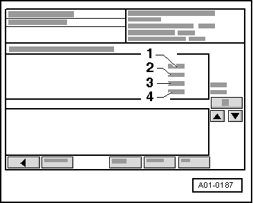
–  Check display in zone -4-.
l  Specification: 1500 … 1600 mbar.
If specification is not obtained:
  A01-0187
FaultPossible causes
Charge pressure below specification
t  Charge pressure control solenoid valve -N75- defective. Checking in „Guided Fault Finding“ → Vehicle diagnostic, testing and information system VAS 5051
t  Hose connections to charge pressure control solenoid valve -N75- defective. Checking → Chapter „Connection diagram for charge pressure control and vacuum control - vehicles to 06.02“ and → Chapter „Connection diagram for charge pressure control and vacuum control - vehicles from 07.02 onwards“
t  Charge pressure regulating valve in turbocharger stuck in open position
t  Leak between turbocharger and intake manifold. Effects → Chapter
t  Mechanical air recirculation valve defective. Checking → Chapter
t  Turbocharger air recirculation valve -N249- defective. Checking in „Guided Fault Finding“ → Vehicle diagnostic, testing and information system VAS 5051
t  Turbocharger defective. Renewing → Chapter
Charge pressure above specification → Remark
t  Vacuum unit for charge pressure regulating valve defective. Renew turbocharger → Chapter
t  Air leaks in hoses or connections to vacuum unit for charge pressure control (via solenoid valve for charge pressure control -N75-). Checking → Chapter „Connection diagram for charge pressure control and vacuum control - vehicles to 06.02“ and → Chapter „Connection diagram for charge pressure control and vacuum control - vehicles from 07.02 onwards“
t  Charge pressure regulating valve in turbocharger sticking in closed position. Renew turbocharger → Chapter

1)  If the charge pressure is too high the fuel supply will be interrupted in order to protect the engine. Misfiring will then occur at high engine speeds.
   

Effects of leaks > < Connection diagram for charge pressure control and vacuum control - vehicles from 07.02 onwards