| –
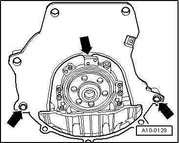
| Check whether both dowel sleeves for centring the engine/gearbox assembly are fitted in the cylinder block; install if necessary. |
| –
| Ensure that the intermediate plate is engaged on the sealing flange and pushed onto the dowel sleeves -arrows-. |
| –
| If fitted, push intermediate plate between engine and gearbox onto dowel sleeves. |
| –
| Attach engine to gearbox and screw in one bolt finger-tight. |
| –
| Fit engine mounting (left-side). |
| –
| Release spindle of support bracket -10 - 222 A-. |
| –
| Lower engine, inserting studs of engine mountings into consoles for engine mountings as you do so. |
| –
| Before securing engine mountings, align engine so that mountings are free of stress by shaking back and forth. |
| –
| Screw in securing bolts for engine/gearbox, noting different bolt lengths as you do so. |
| The remaining installation steps are carried out in the reverse sequence. |
| Vehicles with engine codes AVB, AVF, AWX, BKE: |
| –
| Install catalytic converter together with front exhaust pipe → Chapter. |
| –
| Align exhaust system so it is free of stress → Chapter. |
| Vehicles with engine codes BPW, BRB, BRC: |
| –
| Install front exhaust pipe: vehicles with manual gearbox → Chapter; vehicles with multitronic gearbox → Chapter. |
| –
| Align exhaust system so it is free of stress → Chapter. |
| –
| Install poly V-belt: vehicles up to 05.2003 → Anchor, vehicles from 06.2003 onwards → Anchor. |
|
|
|

 Note
Note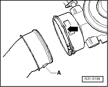
 Caution