audi Workshop Repair Guides

Audi Workshop Service and Repair Manuals

Checking compression - engine codes AVB, AVF and AWX > < Removing and installing cylinder head cover
Removing and installing cylinder head
Special tools and workshop equipment required
   
t  Counterhold tool -T10051-
  W00-0992
t  Puller -T10052-
Removing
  Caution
Observe notes on procedure for disconnecting the battery → Electrical system; Rep. Gr.27.
–  Disconnect earth wire at battery with ignition switched off.
–  Drain off coolant → Chapter.
–  Remove bumper cover (front) → Rep. Gr.63.
–  Move lock carrier to service position → Rep. Gr.50.
  W00-0993
–  Unclip cover caps.
–  Unscrew nuts -arrows- and detach engine cover panel. Also pull out dipstick if necessary.
–  Remove insulation beneath cover panel (if fitted).
  A10-10348
–  Unplug electrical connector -1-.
–  Move aside fuel hoses at air pipe.
–  Remove bolt -2-.
–  Remove air pipe -arrows-.
  A10-1035
–  Detach vacuum line going to brake servo -arrow- at plenum chamber partition panel.
  A10-1127
–  Unplug electrical connector -1- at air mass meter -G70-.
–  Loosen hose clip -2- to remove air intake hose.
–  Move clear wiring harness at air cleaner housing and remove air cleaner housing -arrow-.
  A10-1121
–  Disconnect air intake hose from turbocharger -arrows-.
  A15-0629
Vehicles with engine codes AVB, AVF, AWX:
–  Detach vacuum hoses:
1 - At mechanical EGR valve
2 - At vacuum unit for intake manifold flap
3 - At vacuum unit for charge pressure control
  A15-0630
Vehicles with engine codes BKE, BPW, BRB, BRC:
–  Unplug electrical connectors:
1 - On exhaust gas recirculation valve -N18- with exhaust gas recirculation potentiometer -G212-
2 - On intake manifold flap motor -V157-
  A23-10018
–  Detach coolant hose from exhaust gas recirculation cooler -arrow-.
  A10-10278
–  Disconnect hose -arrow- from vacuum unit for charge pressure control.
  A21-0153
Vehicles with engine codes AVB, AVF, AWX, BKE:
–  Unscrew nuts securing turbocharger to catalytic converter -arrows-.
  A10-0358
–  Loosen nuts on clamp -arrows-.
–  Push the clamp back in order to separate the exhaust system.
–  Disconnect catalytic converter with exhaust pipe from turbocharger.
  Note
Do not bend the flexible joint (de-coupling element) in the exhaust system more than 10°, otherwise it could be damaged.
Vehicles with engine codes BPW, BRB, BRC:
–  Remove front exhaust pipe: vehicles with manual gearbox → Chapter; vehicles with multitronic gearbox → Chapter.
–  Remove particulate filter → Chapter.
  V26-0733
All vehicles:
–  Detach air intake hose from turbocharger by lifting retaining clip -arrow- slightly.
  A21-10022
Vehicles with manual gearbox 012, 01W, 0A9 or multitronic gearbox:
–  Remove bracket for turbocharger -arrows-.
  Note
Illustration shows engine removed.
  A21-0202
–  Detach oil return pipe at turbocharger -arrows-.
  A21-0201
Vehicles with manual gearbox 01E, 01X:
–  Remove bolts -1- and -2- and detach support for turbocharger.
  Note
Place a cloth underneath to catch any escaping oil.
–  Remove oil return pipe -3- at cylinder block.
  A21-10003
All vehicles:
–  Loosen bolt -arrow-.
–  Pull fuel filter upwards out of bracket and lay it aside with fuel hoses connected.
  A15-0631
–  Unbolt bracket for fuel filter -arrows-.
  A15-0632
–  Detach the coolant hoses at the top coolant pipe.
–  Unscrew nut -arrow-.
–  Detach coolant pipe (top) -1-.
–  Detach electrical connectors at glow plugs.
  A19-0225
–  Turn knurled nut -3- for main connector anti-clockwise and unplug main connector.
–  Disconnect fuel hoses -1- and -2-.
–  Move wiring at tandem pump clear.
  A15-0517
–  Unscrew oil supply pipe at oil filter bracket -arrow-.
  A15-0528
–  Detach coolant hose -1- and, if fitted, rear coolant hose-4- at cylinder head.
–  Unplug electrical connector -3-.
–  If fitted, unscrew wiring harness clamp -2-.
  Note
Illustration shows engine removed.
  A15-0633
–  Remove toothed belt:
t  Vehicles with hydraulically damped tensioning roller - engine codes AVB, AVF, AWX → Chapter.
t  Vehicles with friction-damped tensioning roller - engine codes AVB, AVF, AWX → Chapter.
t  Engine codes BKE, BPW, BRB, BRC → Chapter.
–  Remove camshaft sprocket securing bolts -1-.
–  Detach camshaft sprocket from hub.
  N15-0232
–  Loosen securing bolt -1- for hub; use counterhold tool -T10051-.
–  Then unscrew bolt approx. 2 turns.
  N15-0271
–  Apply puller -T10052- and align it with holes in hub.
–  Screw bolts -1- into hub.
–  Apply tension to hub by evenly tightening centre bolt -2- until hub separates from taper of camshaft.
  Note
Use 30 mm spanner to hold puller.
–  Detach hub from taper of camshaft.
  N15-0280
–  Remove toothed belt tensioning roller.
–  Remove bolts -2 ... 4-.
–  Unscrew stud -1- using two M8 locknuts.
  A15-0519
–  Detach crankcase breather hose at pressure control valve -arrow-.
–  Unscrew cylinder head cover bolts in the sequence -13 ... 1- and remove cylinder head cover.
  A15-0635
Vehicles with engine codes BKE, BPW, BRB, BRC:
–  Remove connecting pipe (top) for exhaust gas recirculation -arrows-.
  A15-10175
All vehicles:
–  Loosen cylinder head bolts in the sequence: -1 ... 10-.
–  Carefully lift off the cylinder head with the assistance of a 2nd mechanic.
–  Lay cylinder head aside on a clean surface with the combustion chamber side facing upwards.
  Caution
t  Vehicles with ceramic glow plugs: The ceramic glow plugs fitted in this engine are very easily damaged and project slightly beyond the cylinder head gasket surface, so do NOT lay the cylinder head down on the gasket side while the glow plugs are still installed.
t  Handling ceramic glow plugs → Chapter.
Installing
  Note
t  Carefully remove any sealant residue from the cylinder head and cylinder block. Ensure that no long scores or scratches are made on the surfaces.
t  Carefully remove any remaining emery and abrasive material.
t  No oil or coolant must be allowed to remain in the blind holes for the cylinder head bolts in the cylinder block.
t  Renew the cylinder head bolts.
t  Renew self-locking nuts and bolts when performing assembly work.
t  Renew bolts which are tightened to a specified angle as well as oil seals and gaskets.
t  Do not remove new cylinder head gasket from packaging until it is ready to be fitted.
t  Handle gasket very carefully. Damage to the silicone coating or the indented area will lead to leaks.
t  When installing a replacement cylinder head with fitted camshaft, the contact surfaces between hydraulic tappets and cam running surfaces must be oiled after installing the cylinder head.
t  The plastic protectors fitted to protect the open valves should not be removed until the cylinder head is ready to be fitted.
t  Hose connections and hoses for charge air system must be free of oil and grease before assembly. Do NOT use lubricant.
t  Secure all hose connections with the correct type of hose clips (same as original equipment) → Electronic parts catalogue.
t  To ensure that the charge air hoses can be properly secured at their connections, spray rust remover onto the worm thread of used hose clips before installing.
t  Removing and installing tandem pump → Rep. Gr.20.
t  After fitting a new cylinder head or cylinder head gasket, change the engine oil and refill the complete cooling system with fresh coolant.
  N15-0026
–  Check whether the camshaft and the crankshaft are positioned at TDC:
l  The cams for cylinder 1 must point upwards evenly on camshaft -arrows-.
  A15-0530
l  The crankshaft sprocket must be locked in position:
A - For engine codes AVB, AVF, AWX: with crankshaft stop -T10050-
B - For engine codes BKE, BPW, BRB, BRC: with crankshaft stop -T10100-
  Note
The markings on the toothed belt sprocket and the crankshaft stop -arrow- must align. The pin of the crankshaft stop must engage in the aperture in the sealing flange.
  N15-10159
–  Note identification markings on cylinder head gasket.
t  Part No. = -arrow 1-
t  Production code = -arrow 2- (can be disregarded)
t  Holes = -arrow 3-
  Note
t  If the cylinder head gasket or cylinder head is renewed, be sure to install a gasket with the same identification.
t  If parts of the crankshaft drive have been renewed, the new cylinder head gasket must be selected by measuring the piston projection at TDC → Chapter.
  A15-0802
–  Fit cylinder head gasket.
l  Note centring sleeves -arrows- in cylinder block.
l  Check installation position of cylinder head gasket: the word “oben” (top) or the Part No. should face towards the cylinder head.
  A15-0522
–  Fit the cylinder head.
–  Check that all washers for cylinder head bolts are fitted in cylinder head.
–  Insert new cylinder head bolts and tighten finger-tight.
–  Tighten cylinder head bolts in 4 stages in the sequence indicated:
1.  Tighten with torque wrench to 40 Nm.
2.  Tighten with torque wrench to 60 Nm.
3.  Use rigid wrench to turn 90° further.
4.  Use rigid wrench to turn 90° further.
  Note
Cylinder head bolts do not have to be torqued down again later after repair work.
  V15-0738
–  Apply locking fluid to bolts -2 … 4- and tighten bolts; for locking fluid refer to → Electronic parts catalogue.
–  Screw in stud -1- using two M8 locknuts.
  A15-0519
–  Attach hub to camshaft.
–  Tighten securing bolt -1- (use counterhold -T10051-).
  N15-0271
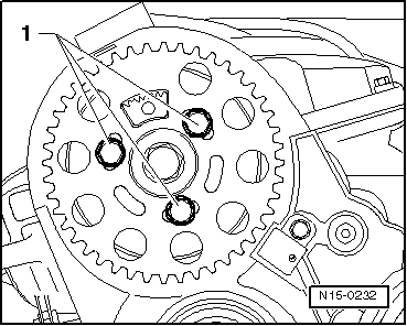
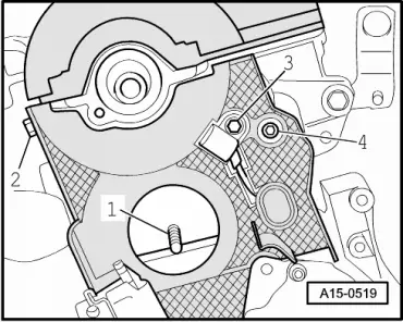
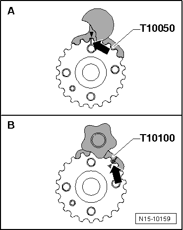
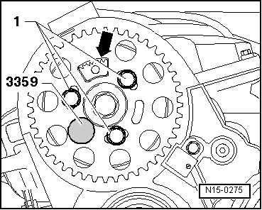
–  Push camshaft sprocket onto hub.
l  Toothed segment -arrow- of camshaft sprocket must be at top.
–  Screw in bolts -1- finger-tight.
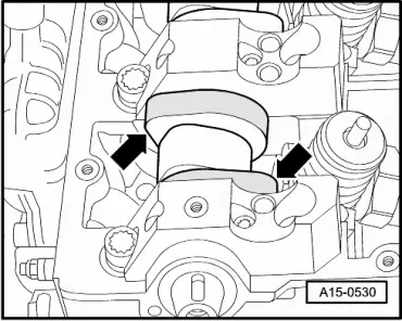
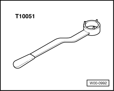
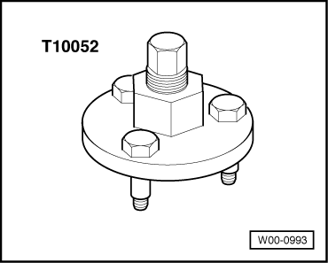
–  Lock hub with locking pin -3359-.
The remaining installation steps are carried out in the reverse sequence.
–  Install cylinder head cover → Anchor.
–  Fit toothed belt (adjust valve timing):
t  Vehicles with hydraulically damped tensioning roller - engine codes AVB, AVF, AWX → Anchor.
t  Vehicles with friction-damped tensioning roller - engine codes AVB, AVF, AWX → Anchor.
t  Engine codes BKE, BPW, BRB, BRC → Anchor.
  Note
Follow all instructions for removing and installing toothed belt.
–  Install vibration damper: vehicles up to 05.2003 → Anchor, vehicles from 06.2003 onwards → Anchor.
–  Install viscous fan → Chapter.
–  Install poly V-belt: vehicles up to 05.2003 → Anchor, vehicles from 06.2003 onwards → Anchor.
–  Install coolant pipe (top) → Chapter.
Vehicles with engine codes AVB, AVF, AWX, BKE:
–  Install catalytic converter together with front exhaust pipe → Chapter.
–  Align exhaust system so it is free of stress → Chapter.
Vehicles with engine codes BPW, BRB, BRC:
–  Install particulate filter → Chapter.
–  Install front exhaust pipe: vehicles with manual gearbox → Chapter; vehicles with multitronic gearbox → Chapter.
–  Align exhaust system so it is free of stress → Chapter.
  N15-0275
All vehicles:
–  When installing air intake hoses with plug-in connectors, ensure that the securing clip -arrow- engages audibly on the retaining lug -A-.
–  Install lock carrier with attachments → Rep. Gr.50.
–  Install bumper cover (front) → Rep. Gr.63.
–  Electrical connections and routing → Current flow diagrams, Electrical fault finding and Fitting locations.
–  Observe notes on procedures required after connecting battery → Electrical system; Rep. Gr.27.
–  Change engine oil → Booklet803 or → Booklet805.
–  Fill cooling system with fresh coolant → Anchor.
Tightening torques
  N21-0184
ComponentNm
Toothed belt coverM610 1)
(rear) to cylinder headM825
Hall sender to cylinder head10 1)
Stud to cylinder head15
Hub to camshaft100
Oil supply pipe to oil filter bracket25
Oil return pipe to turbocharger15 2)
Top coolant pipe to lifting eye20
Bracket for turbocharger to:Turbocharger20
Engine support (with manual gearbox 012, 01W, 0A9 or multitronic gearbox)25
 Cylinder block (with manual gearbox 01E, 01X)40
Oil return pipe to cylinder block30
Fuel filter bracketM610
to cylinder headM715
to cylinder blockM820
Connecting pipe (top) to:Intake manifold22
Exhaust gas recirculation cooler22
Hose clipsWidth 9 mm3
Width 13 mm5.5
l  1) Apply locking fluid when installing; refer to → Electronic parts catalogue for locking fluid.
l  2) Property class 10.9; use only genuine bolts (same as original parts) → Electronic parts catalogue.


Checking compression - engine codes AVB, AVF and AWX > < Removing and installing cylinder head cover