audi Workshop Repair Guides

Audi Workshop Service and Repair Manuals

Checking hydraulic bucket tappets > < Renewing valve stem oil seals with cylinder head installed
Renewing valve stem oil seals with cylinder head removed
   
Renewing valve stem oil seals with cylinder head removed
Special tools and workshop equipment required
t  Puller -3047 A-
t  Fitting tool -3129-
t  U/J extension and socket, 10 mm -3220-
t  Removal and installation device for valve cotters -VAS 5161-

   
t  Engine and gearbox support -VAS 6095-
t  Cylinder head tensioning device -VAS 6419-
  W00-1273
Procedure
Different types of glow plugs can be installed in 4-cylinder 2-valve TDI engines in Audi A4 vehicles.
Engine codes AVB, AVF, AWX, BRB:
t  These engines are fitted exclusively with metal glow plugs.
Engine codes BKE, BPW, BRC:
t  These engines can be fitted with either metal or ceramic glow plugs.
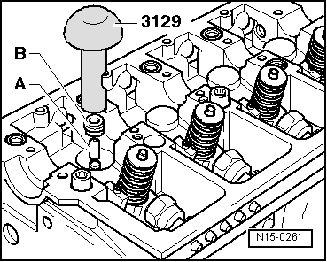
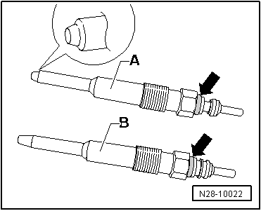
A - Bosch ceramic glow plugs are colour-coded with a “white seal”-arrow- and have a chamfered shoulder (⇒ detail view) at the tip.
A - NGK ceramic glow plugs are colour-coded with a “white seal (on some versions painted over in silver)”-arrow- but do not have a chamfered shoulder at the tip.
B - Metal glow plugs are colour-coded with a “red seal”-arrow-.
  Caution
Important: Always observe the special instructions for handling ceramic glow plugs. The metal glow plugs do not require any special handling procedures.
Vehicles with ceramic glow plugs:
  Caution
t  Due to the special properties of the material used, ceramic glow plugs are easily damaged and require extra care when handling and removing/installing. Always observe the special instructions when removing and installing ceramic glow plugs → Rep. Gr.28.
t  Transport and store only in original packaging or packed separately in bubble wrap.
t  Do not remove new ceramic glow plugs from packaging until they are ready to be fitted.
t  Ceramic glow plugs are sensitive to knocks and bending. For this reason, ceramic glow plugs which have been dropped (even from a height of only about 2 cm) must not be installed, even if no damage is apparent (hair-line cracks may not be visible).
t  Always install a new ceramic glow plug if you are not sure the old one is in perfect condition.
t  Damaged glow plugs (e.g. heater pin of the glow plug is damaged) will invariably cause engine damage.
t  If the heater pin of the glow plug is damaged, the fragments must be removed from the combustion chamber before starting the engine for the first time, otherwise this will invariably cause mechanical damage (piston seizure).
t  The software of the engine control unit is programmed specifically for either the ceramic or the metal glow plugs, so it is important to install the correct type.
t  Mixed installation of ceramic glow plugs and metal glow plugs on the same engine is not permissible.
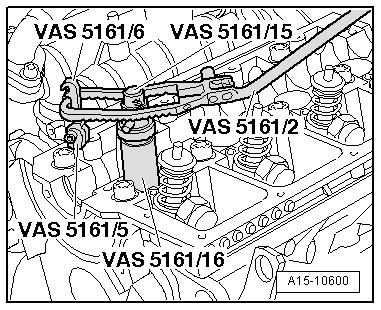
All vehicles:
–  Remove the camshaft → Chapter.
–  Remove camshaft bearing shells from cylinder head.
  Note
t  Make sure that the used camshaft bearing shells are not interchanged (note marking).
t  Make sure that the hydraulic bucket tappets are not interchanged; mark allocation on rear with a waterproof felt-tipped pen.
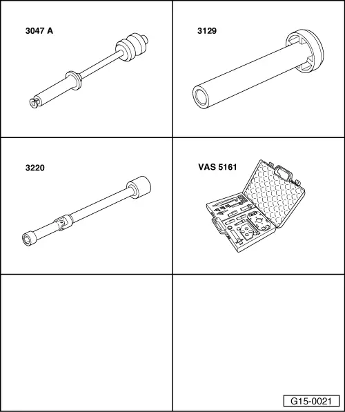
–  Unscrew all glow plugs using U/J extension and socket, 10 mm -3220-.
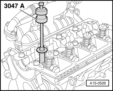
–  Remove bucket tappets out of guides.
–  Place bucket tappets down on a clean surface with contact surface facing downwards in the order in which they were removed.
  N28-10022
–  Attach tensioning device -VAS 6419- to engine and gearbox support -VAS 6095-.
–  Secure cylinder head in tensioning device -VAS 6419- as illustrated.
–  Connect compressed air line to tensioning device -VAS 6419-.
–  Using lever -arrow-, slide air pad under combustion chamber where valve stem oil seal is to be removed.
–  Apply just enough compressed air to bring air pad into contact with valve heads.
  A15-10529
–  Insert punch -VAS 5161/3- in bucket tappet guide.
–  Knock valve cotters loose on all valves using a plastic hammer.
  A15-0524
–  Screw snap-in device -VAS 5161/6- with interlocking fork (M6) -VAS 5161/5- into threaded hole on cylinder head.
–  Push guide bush -VAS 5161/16- as far as it will go into bucket tappet guide on valve to be removed.
l  Installation position of guide bush: hatched areas are perpendicular to driving direction.
–  Insert assembly cartridge -VAS 5161/15- into guide bush.
–  Attach pressure fork -VAS 5161/2- to snap-in device -VAS 5161/6- and push assembly cartridge downwards.
–  At the same time, turn knurled screw of assembly cartridge clockwise until tips engage in valve cotters.
–  Move knurled screw back and forth slightly; the valve cotters are thus forced apart and taken up by the cartridge.
–  Release pressure fork.
–  Remove assembly cartridge and guide bush.
–  Remove valve spring plate and valve springs.
  A15-10600
–  Detach valve stem oil seals using puller -3047 A-.
  Note
  A15-0526
A plastic sleeve -A- is included with the new valve stem oil seals.
–  Insert plastic sleeve -A- onto the valve stem to prevent damage to the new valve stem oil seal -B-.
–  Lightly lubricate sealing lip of valve stem oil seal.
–  Slip valve stem oil seal over plastic sleeve.
–  Carefully press valve stem oil seal down onto valve guide using fitting tool -3129-.
–  Remove the plastic sleeve.
  N15-0261
–  If valve cotters had been removed from assembly cartridge they must first be inserted in insertion device -VAS 5161/18-.
  Note
Larger diameter of valve cotters faces upwards.
–  Press assembly cartridge -VAS 5161/15- onto insertion device from above and pick up valve cotters.
–  Insert valve springs and valve spring plate.
  A15-0445
–  Re-insert assembly cartridge in guide bush -VAS 5161/16-.
–  Push pressure fork down and pull knurled screw upwards while turning to left and right – this will insert the valve cotters.
–  Release the pressure fork with knurled screw still in pulled position.
–  Repeat procedure for each valve.
Assembling
Installation is carried out in the reverse order; note the following:
–  Insert bucket tappets.
–  Install camshaft → Anchor.
–  Install glow plugs → Rep. Gr.28.
  A15-10600

Checking hydraulic bucket tappets > < Renewing valve stem oil seals with cylinder head installed