
A4 Cabriolet Mk2
| Removing and installing toothed belt |
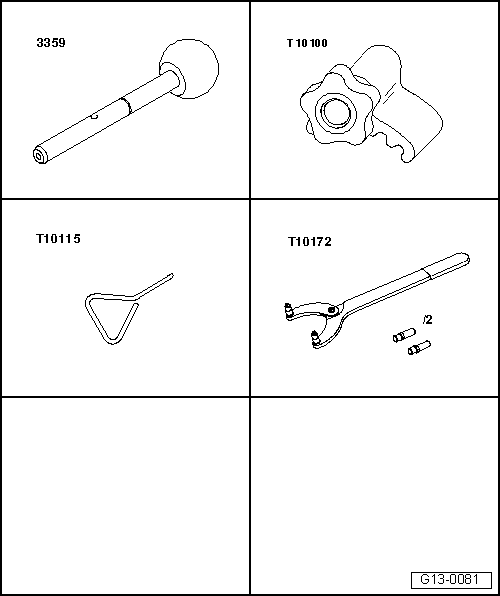
| Special tools and workshop equipment required |
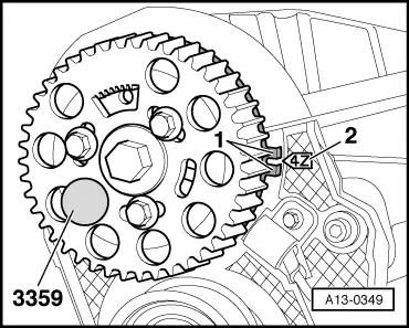
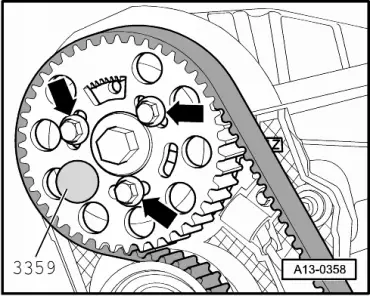
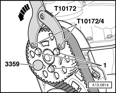
| t | Diesel injection pump locking pin -3359- |
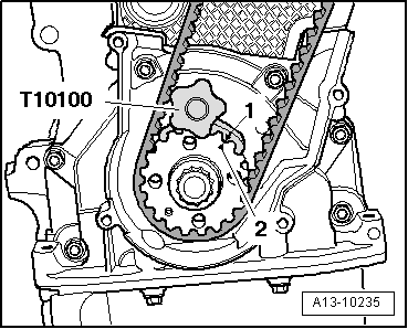
| t | Crankshaft stop -T10100- |
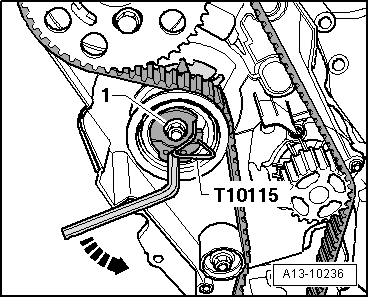
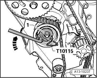
| t | Locking pin -T10115- |
| t | Counterhold tool -T10172- with pin -T10172/4- |
| t | Locking fluid → Electronic parts catalogue |
|
|
|
|
|
|
 Note
Note |
|
|
|
|
|
|
|
Note
|
|
 Caution
Note
|
|
Note
|
|
|
|
Note
|
|
|
|
|
|
Note
Note
Note
|
|
|
|
Note
|
|
|
|
Note
|
|
Note
|
|
| Component | Nm | ||
| Camshaft sprocket to hub | 25 | ||
| Tensioning roller for toothed belt to cylinder head | 20 + 45° | ||
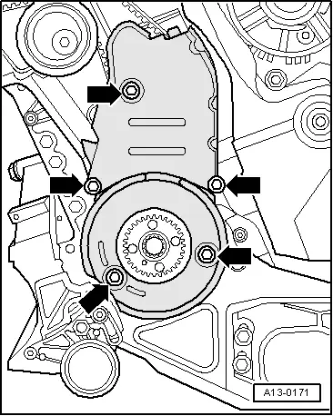
| Toothed belt cover (bottom) to cylinder block | 10 1) | ||
| Toothed belt cover (centre) to cylinder block | 10 1) | ||
| |||