| Component | Nm |
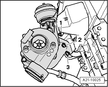
| Turbocharger to exhaust manifold | 25 1)2) |
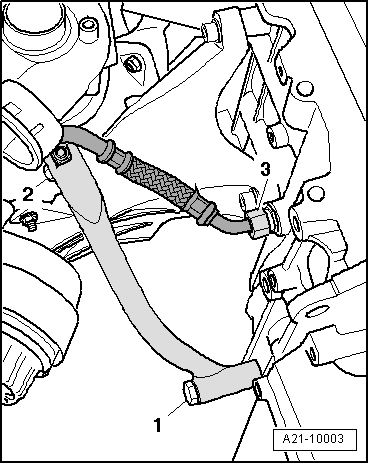
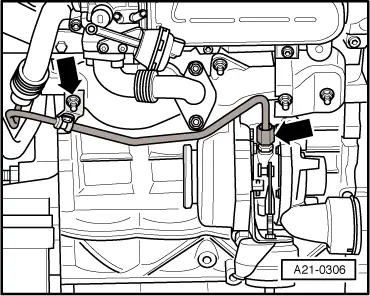
| Oil supply pipe to turbocharger | 22 |
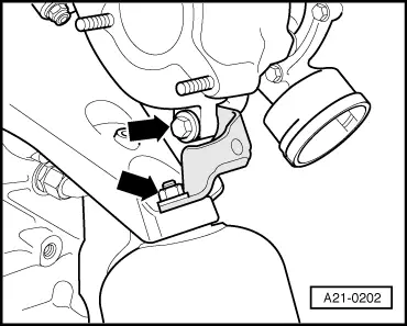
| Bracket for turbocharger to turbocharger (vehicles with manual gearbox 012, 01W, 0A9 and multitronic gearbox) | 20 |
| Bracket for turbocharger to engine support (vehicles with manual gearbox 012, 01W, 0A9 and multitronic gearbox) | 25 |
| Oil return pipe to turbocharger (vehicles with manual gearbox 012, 01W, 0A9 and multitronic gearbox) | 15 |
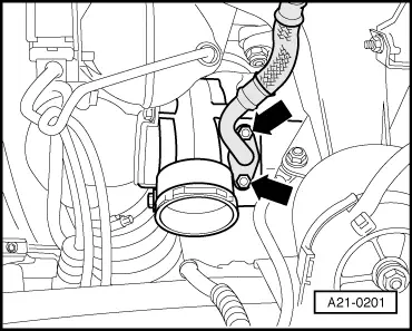
| Support for turbocharger to turbocharger (vehicles with manual gearbox 01E, 01X) | 20 |
| Support for turbocharger to cylinder block (vehicles with manual gearbox 01E, 01X) | 30 |
| Oil return pipe to cylinder block (vehicles with manual gearbox 01E, 01X) | 40 |
| Oil supply pipe to bracket | 10 |
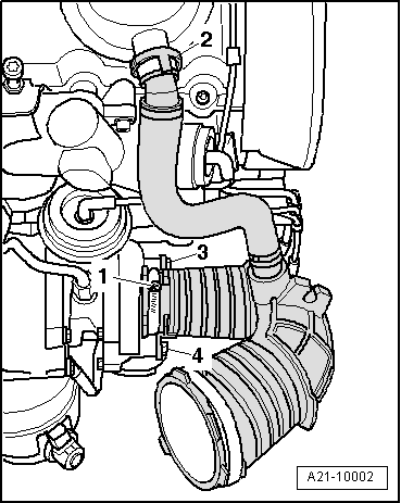
| Air intake hose to turbocharger | 8 |
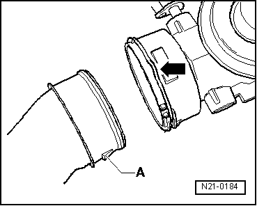
| Hose clips | Width 9 mm | 3 |
| Width 13 mm | 5.5 |
|

 Caution
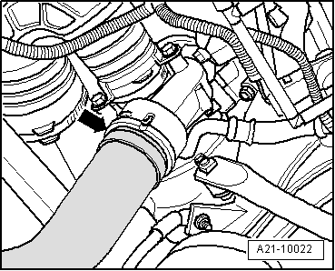
 Note
Note