
A4 Cabriolet Mk2
| Removing engine |
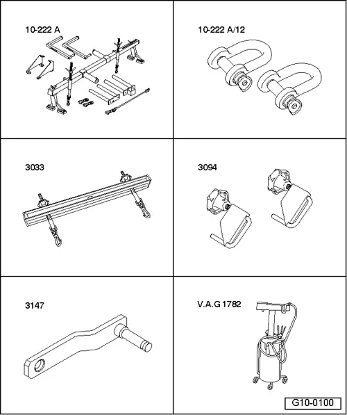
| Special tools and workshop equipment required |
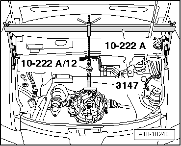
| t | Support bracket -10-222 A- |
| t | Shackle -10-222 A/12- |
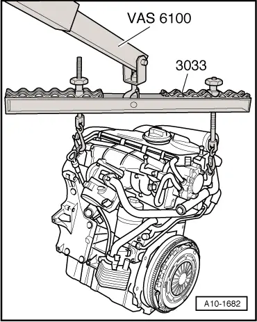
| t | Lifting tackle -3033- |
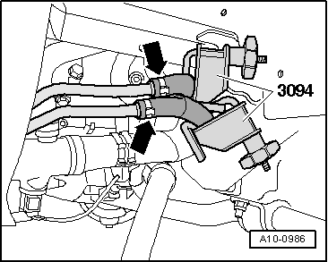
| t | Hose clamps for hoses up to 25 mm Ø -3094- |
| t | Gearbox support -3147- |
| t | Used oil collection and extraction unit -V.A.G 1782- |
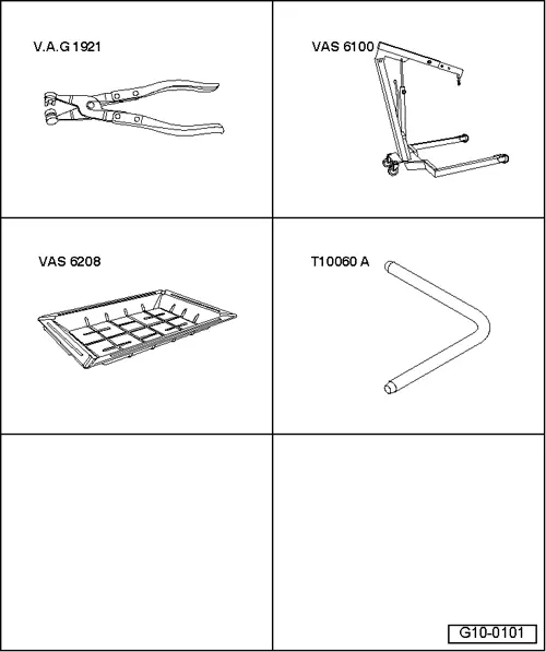
| t | Hose clip pliers -V.A.G 1921- |
| t | Workshop hoist -VAS 6100- |
| t | Drip tray for workshop hoist -VAS 6208- |
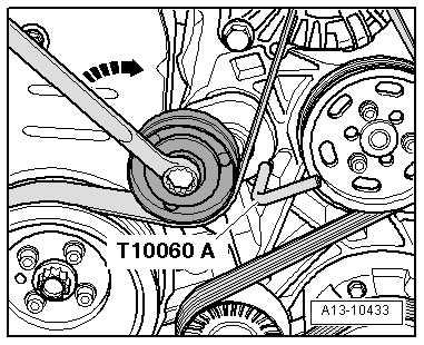
| t | Locking pin -T10060 A- |
| t | Safety goggles |
| t | Protective gloves |
 Note
Note
|
 Caution
|
|
 WARNING
|
|
|
|
|
|
|
|
|
|
|
|
|
|
|
|
|
|
Note
|
|
|
|
Note
|
|
|
|
|
|
|
|
|
|
|
|
Note
|
|
|
|
|
|
Note
|
|
|
|
Note
|
|
|
|
|
|
|
|
|
|
|
|
Note
|
|
Note |
|
|
|
|
|
|
|
|
|
|
|
|
|
|
|
|
|
|
|
|
|
|
|
|
|
|
|
Note
|
|
|
|
|
|
Note |
|
|

|
|
|
|
|
Note
|
|
|
|
|
|
Note
|
|
Note
|
|
Note
|
|
|
|
|
|
|
|
|
|
Note
|
|
Note
|
|