audi Workshop Repair Guides

Audi Workshop Service and Repair Manuals

Checking hydraulic valve compensation elements > < Renewing valve stem oil seals with cylinder head installed
Renewing valve stem oil seals with cylinder head removed
Special tools and workshop equipment required
   
t  Valve stem seal puller -3364-
  W00-0302
t  Valve stem seal fitting tool -3365-
  W00-0194
t  Removal / installing device for valve cotters -VAS 5161- with knurled spacer ring -VAS 5161/23-1- and guide plate -VAS 5161/23-
  W00-1050
t  Engine and gearbox support -VAS 6095-
t  Cylinder head clamping device -VAS 6419-
Procedure
–  Remove camshafts → Chapter.
–  Mark original positions of rocker fingers and hydraulic compensation elements for reinstallation.
–  Remove rocker fingers together with hydraulic compensation elements and put down on a clean surface.
–  Insert cylinder head clamping device -VAS 6419- into engine and gearbox support -VAS 6095-.
  W00-1273
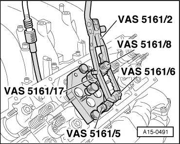
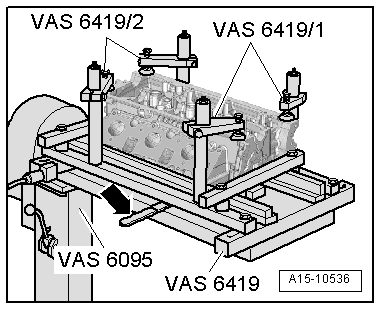
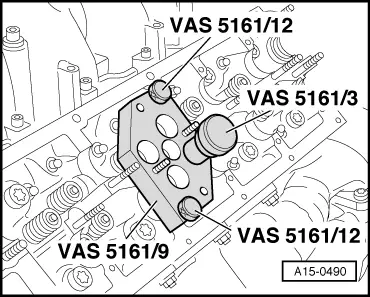
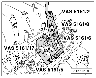
–  Secure cylinder head in cylinder head clamping device as illustrated.
–  Connect cylinder head clamping device to compressed air.
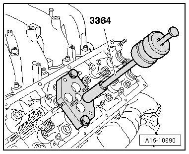
–  Using lever -arrow-, slide air pad under combustion chamber where valve stem oil seal is to be removed.
–  Apply just enough compressed air to bring air pad into contact with valve heads.
  A15-10536
–  Fit guide plate -VAS 5161/9- onto cylinder head.
–  Secure guide plate with knurled screws -VAS 5161/12-.
–  Apply drift -VAS 5161/3- to guide plate and use plastic-headed hammer to release sticking valve cotters.
  A15-0490
–  Screw snap-in device -VAS 5161/6- with engaging fork -VAS 5161/5- into guide plate.
–  Slide knurled spacer ring -VAS 5161/17- onto assembly cartridge -VAS 5161/8-.
–  Attach pressure fork -VAS 5161/2- to snap-in device and push assembly cartridge down.
–  At the same time, turn knurled screw of assembly cartridge clockwise until tips engage in valve cotters.
–  Move knurled screw back and forth slightly; the valve cotters are thus forced apart and taken up by the assembly cartridge.
–  Release pressure fork.
–  Take off assembly cartridge with knurled spacer ring.
–  Detach valve spring with valve spring plate.
  A15-10689
–  Pull off valve stem oil seal with valve stem seal puller -3364-.
  A15-10690
  Caution
Make sure valve stem oil seals are not damaged when installing.
New valve stem oil seals -B- are supplied with plastic sleeve; fit plastic sleeve -A- onto valve stem.
–  Lightly oil sealing lip of valve stem oil seal.
–  Slide valve stem oil seal onto plastic sleeve.
–  Carefully press valve stem oil seal onto valve guide using valve stem seal fitting tool -3365-.
–  Take off plastic sleeve.
  A15-0282
If valve cotters had been removed from assembly cartridge they must first be inserted in insertion device -VAS 5161/18-.
l  Larger diameter of valve cotters faces upwards.
–  Insert valve spring and valve spring plate.
–  Press assembly cartridge onto insertion device from above and take up valve cotters.
  A15-0445
–  Insert assembly cartridge in guide plate -VAS 5161/9- again.
–  Press down pressure fork and pull knurled screw upwards while turning screw in both directions - this will insert the valve cotters.
–  Release the pressure fork with knurled screw still in pulled position.
–  Repeat procedure for each valve.
Assembling
Installation is carried out in the reverse order; note the following:
–  Install camshafts → Chapter.
  A15-0491

Checking hydraulic valve compensation elements > < Renewing valve stem oil seals with cylinder head installed