audi Workshop Repair Guides

Audi Workshop Service and Repair Manuals

Removing and installing oil pump > < Sump, oil pump - exploded view of components
Removing and installing sump (bottom section)
Special tools and workshop equipment required
   
t  Used oil collection and extraction unit -V.A.G 1782-
  W00-10211
t  Drip tray for workshop hoist -VAS 6208- or -V.A.G 1306-
t  Electric drill with plastic brush attachment
t  Safety goggles
t  Sealant → Parts catalogue
Removing
  Note
All cable ties which are released or cut open when removing must be fitted in the same position when installing.
  WARNING
Hot steam or hot coolant can escape when expansion tank is opened; cover filler cap with cloth and open carefully.
–  Open filler cap on coolant expansion tank.
  W00-10228
–  On vehicles with auxiliary/additional heater, remove bolts -arrows- securing exhaust pipe for auxiliary/additional heater to noise insulation.
  A10-0407
–  Release quick-fasteners -1- and -2- and take off front noise insulation. Leave rear noise insulation in position.
  A10-1320
–  Place drip tray for workshop hoist -VAS 6208- or -V.A.G 1306- under engine.
–  Open drain plug -arrow- and drain off coolant.
  A19-0087
–  If fitted, unscrew bolts -2- and -3- and remove brace.
–  Slacken off bolt -1- and detach coolant drain pipe from cylinder block.
  A19-10165
–  Unbolt refrigerant pipe bracket -arrow- from sump.
  A10-1087
–  Remove bracket -arrow- for gear oil pipes/ATF pipes.
  A37-0519
–  Unplug electrical connector at oil level/temperature sender -G266--arrow-.
–  Move wiring clear.
  A17-0158
–  Unbolt anti-roll bar mountings -1- and -2-.
–  Lower anti-roll bar.
–  Place used oil collection and extraction unit -V.A.G 1782- under engine.
–  Drain off engine oil.
  A21-0251
–  Unscrew bolts and remove bottom section of sump -1- carefully.
  Note
Pay attention to chain guard in sump when detaching sump (bottom section).
  A17-0108
Installing
Installation is carried out in the reverse order; note the following:
  Note
t  Renew seals and O-rings.
t  Fit all cable ties in the original positions when installing.
–  Remove remaining sealant on bottom and top section of sump with a rotating plastic brush or similar.
  WARNING
Wear safety goggles.
–  Clean sealing surfaces; they must be free of oil and grease.
  Note
The sump (bottom section) must be installed within 5 minutes after applying sealant.
  A17-0159
–  Cut off nozzle of tube at front marking (Ø of nozzle approx. 3 mm).
  A17-0081
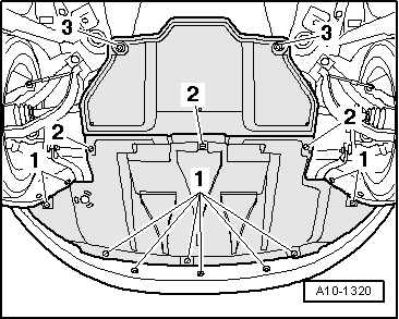
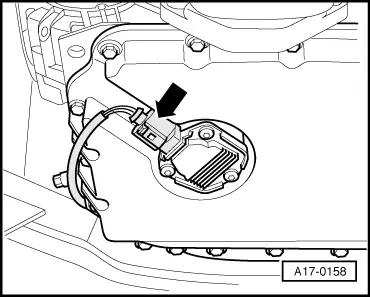
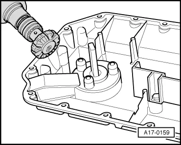
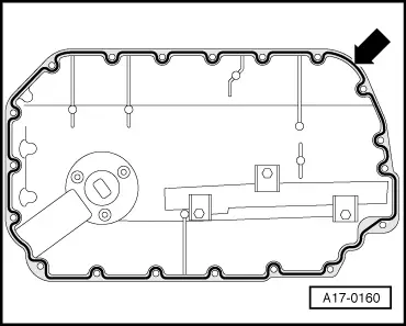
–  Apply the bead of sealant onto the clean sealing surface of the sump (bottom section) as illustrated.
l  Width of sealant bead -arrow-: 2 ... 3 mm.
  Note
Sealant bead must not be wider than 3 mm, otherwise excess sealant could ingress into sump and clog strainer in oil intake pipe.
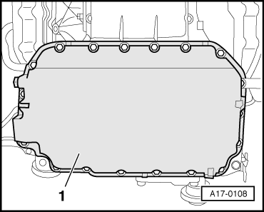
–  Fit sump (bottom section) and tighten all bolts initially to 5 Nm in diagonal sequence.
–  Tighten bolts securing sump (bottom section) to 10 Nm in diagonal sequence.
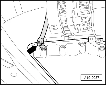
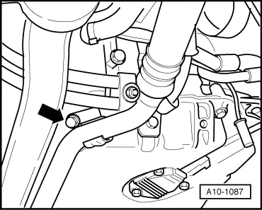
–  Fit new O-ring and locate coolant drain pipe carefully on cylinder block and press it as far as it will go into drilling using a lever.
–  Install anti-roll bar → Running gear, front-wheel drive and four-wheel drive; Rep. Gr.40.
–  Fill cooling system → Anchor.
–  Fill up with engine oil and check oil level → Chapter.
Tightening torques
  A17-0160
ComponentNm
Sump (bottom section) to sump (top section)10
Coolant drain pipe to: Sump10
 Cylinder block40
Drain plug to coolant drain pipe10
Oil drain plug25


Removing and installing oil pump > < Sump, oil pump - exploded view of components