
A4 Cabriolet Mk2
 Note
Note
|
|
|
 Caution
Note
|
|
|
|
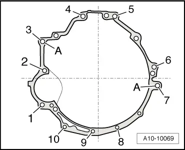
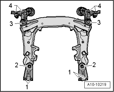
| Item | Bolt | Nm | ||
| 1 | M10x115 | 65 1) | ||
| 2, 6 | M12x125 | 65 | ||
| 3, 5 | M12x110 | 65 | ||
| 4 | M12x115 | 65 | ||
| 7 | M12x140 | 65 | ||
| 8, 9, 10 | M10x80 | 45 | ||
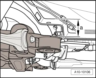
| A | Dowel sleeves for centralising | |||
| ||||
|
|
|
Note
|
|
|
|
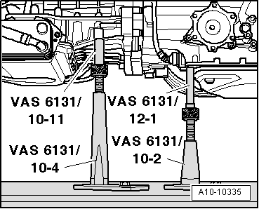
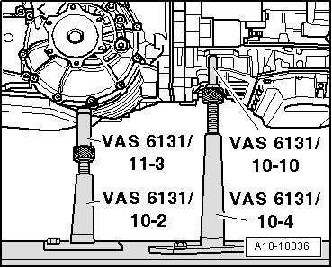
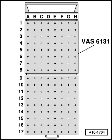
| Platform coordinates | Parts of support set for Audi -VAS 6131/10- | |||||||
| B4 1) | /10-1 | /10-4 | /10-5 | /10-11 | ||||
| G4 1) | /10-1 | /10-4 | /10-5 | /10-12 | ||||
| B11 | /10-1 | /10-2 | /10-5 | /10-8 2) | ||||
| G11 | /10-1 | /10-2 | /10-5 | /11-8 2) | ||||
| D15 1) | /10-1 | /10-3 | /10-5 | /10-12 | ||||
| F15 1) | /10-1 | /10-3 | /10-5 | /10-12 | ||||
| ||||||||
|
|
|
|
|
|
|
|
Note
|
|
|
|
 WARNING
|
|
|
|
Note
Note
|
|
| Component | Nm | |||
| Bolts/nuts | M6 | 9 | ||
| M8 | 20 | |||
| M10 | 40 | |||
| M12 | 65 | |||
| Except for the following: | ||||
| Drive plate to torque converter | 85 1) | |||
| Terminal B+ to starter | 16 | |||
| Engine support to cylinder block | 40 | |||
| Gearbox mounting to subframe | 23 | |||
| Console for engine mounting to longitudinal member | 75 | |||
| Engine mounting to console for engine mounting | 23 | |||
| Drive shaft heat shield to gearbox | 23 | |||
| Torque reaction support to engine | 40 | |||
| Stop for torque reaction support to lock carrier | 28 | |||
| Hydraulic pressure line to power steering pump | 47 | |||
| Fuel hose to fuel line | 22 | |||
| Hose clips (9 mm wide) | 3 | |||
| ||||