
A4 Cabriolet Mk2
|
 Note
Note
|
|
|
|
|
|
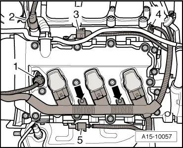
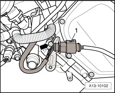
Note |
|
|
|
|
|
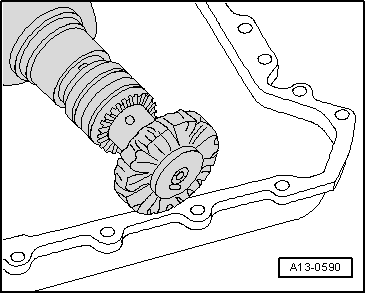
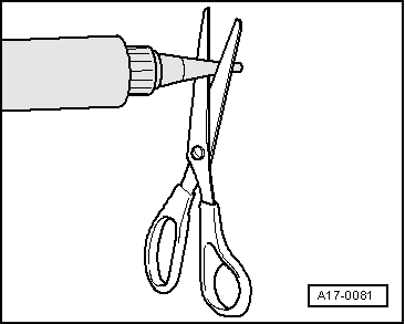
 Caution
|
|
|
|
|
|
|
|
|
|
|
|
|
|
|
|
Note
|
|
|
|
 WARNING
Note |
|
|
|
|
|
|
|
|
|
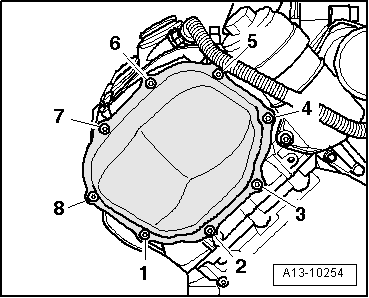
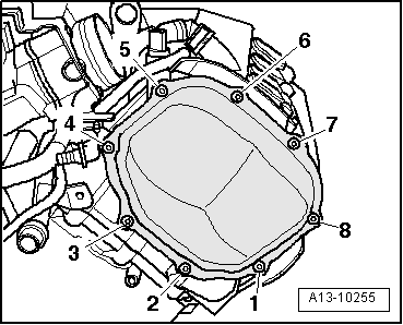
| Component | Nm | ||||
| Timing chain covers (left and right) to engine | 5 + 90° 1)2) | ||||
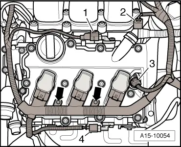
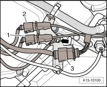
| Bracket for electrical connectors to cylinder head | 9 | ||||
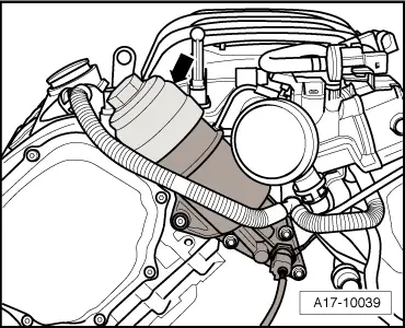
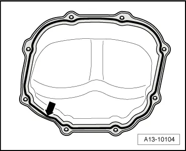
| Sealing cap on oil filter housing | 25 | ||||
| Hose clips (9 mm wide) | 3 | ||||
| |||||