audi Workshop Repair Guides

Audi Workshop Service and Repair Manuals

Removing and installing exhaust manifold (right-side) > < Exhaust manifold - exploded view of components
Removing and installing exhaust manifold (left-side)
Special tools and workshop equipment required
   
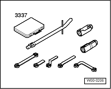
t  Lambda probe open ring spanner set -3337-
  W00-0206
Removing
  Note
All cable ties which are released or cut open when removing must be refitted in the same position when installing.
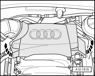
–  Pull off engine cover panel (rear) -arrows-.
  A10-1515
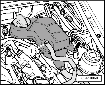
–  Unbolt coolant expansion tank -arrow-.
–  Unplug electrical connector for coolant shortage indicator switch -F66- at bottom of expansion tank and move expansion tank to one side with coolant hoses -1- and -2- attached.
  A19-10068
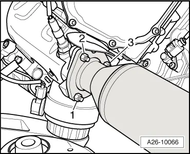
–  Unscrew nut -2- (accessible from above) securing front exhaust pipe to exhaust manifold on the relevant side.
  Note
Shown from rear with engine removed for illustration purposes.
–  Drain off coolant → Chapter.
–  Remove front left wheel.
  A26-10066
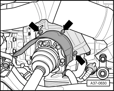
–  Unbolt heat shield -arrows- for drive shaft (left-side).
  A37-0630
–  Unscrew nuts -1- and -3- (accessible from below) connecting front exhaust pipe to exhaust manifold.
  Note
Shown in illustration with engine removed.
  Note
  A26-10066
To avoid any damage, the flexible joint in the front exhaust pipe must not be bent more than 10°.
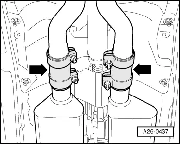
–  Disconnect exhaust system at clamp -left arrow-.
–  Push clamp back and pull front exhaust pipe off exhaust manifold.
  Note
The front exhaust pipe remains on the vehicle.
  A26-0437
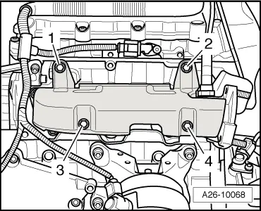
–  Unscrew securing bolts -3- and -4- for heat shield (accessible from below).
  A26-10068
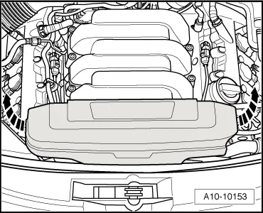
–  Pull off engine cover panel (front) -arrows-.
  A10-10153
–  Detach coolant hose -arrow- from coolant pipe (front).
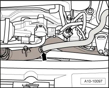
  A10-10097
–  Remove coolant hose (front left) in engine compartment -arrows-.
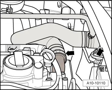
  A10-10110
–  Detach coolant hose -arrow- from coolant pipe (front).
  Note
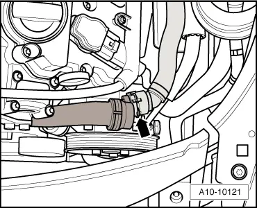
  A10-10121
Lay a cloth under the hydraulic pipe to catch any escaping hydraulic fluid.
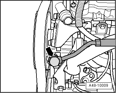
–  Disconnect hydraulic pressure pipe -arrow- at power steering pump, lift clear and place pipe on longitudinal member.
  A48-10009
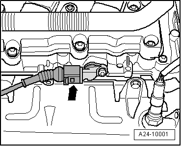
–  Unplug electrical connector -arrow- at Hall sender 4 -G301-.
–  Move wiring clear.
  A24-10001
–  Unscrew securing bolts -1- and -2- for heat shield (accessible from above).
–  Remove the heat shield.
  A26-10068
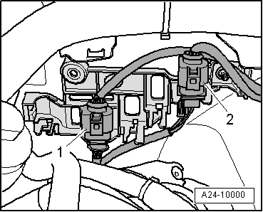
–  Unplug electrical connector -2- for Lambda probe 2 -G108- and move wiring clear.
  Note
Disregard -item 1-.
  A24-10000
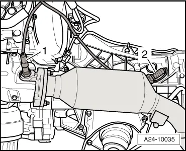
–  Unscrew Lambda probe -1- using Lambda probe open ring spanner set -3337-.
  Note
t  Shown in illustration with engine removed.
t  Disregard -item 2-.
  A24-10035
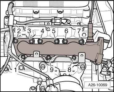
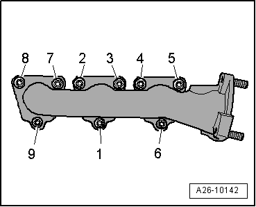
–  Remove nuts -1- and -8- and detach bracket for heat shield.
–  Unscrew nuts -2 ... 7- and -9- and remove exhaust manifold.
Installing
Installation is carried out in the reverse order; note the following:
  Note
t  Renew gaskets, seals and self-locking nuts.
t  Secure all hose connections with the correct type of hose clips (same as original equipment) → Electronic parts catalogue.
t  Reinstall all cable ties in the same locations when assembling.
  A26-10069
–  Secure exhaust manifold together with bracket for heat shield by tightening nuts in 2 stages in the sequence shown, as follows:
1 - Initially tighten to 15 Nm.
2 - Tighten to 25 Nm.
–  Install Lambda probe → Rep. Gr.24.
–  Install front exhaust pipe (left-side) with catalytic converter: vehicles with manual gearbox → Chapter; vehicles with automatic gearbox → Chapter.
–  Align exhaust system so it is free of stress → Chapter.
  A26-10142
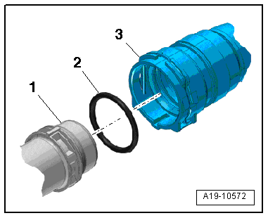
–  Remove old O-ring -2- from coolant hose -3-.
–  Lubricate new O-ring with coolant additive and fit O-ring in coolant hose.
–  Press coolant hose onto coolant pipe -1- until it engages with a click.
–  Press coolant hose in again and then pull to check that plug-in connector is correctly engaged.
–  Fill cooling system → Anchor.
–  Check fluid level of power steering and top up if necessary → Rep. Gr.48.
Tightening torques
  A19-10572
ComponentNm
Exhaust manifold to cylinder head25 1)2)
Heat shield to bracket for heat shield10
Hydraulic pressure line to power steering pump47
Drive shaft heat shield to gearbox23
l  1) Renew nuts.
l  2) Grease with high-temperature paste; refer to → Electronic parts catalogue for high-temperature paste


Removing and installing exhaust manifold (right-side) > < Exhaust manifold - exploded view of components