audi Workshop Repair Guides

Audi Workshop Service and Repair Manuals

Enginecrankshaft group, pistons > < Securing engine to assembly stand
Installing engine
Installing engine
Special tools and workshop equipment required
t  
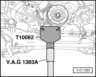
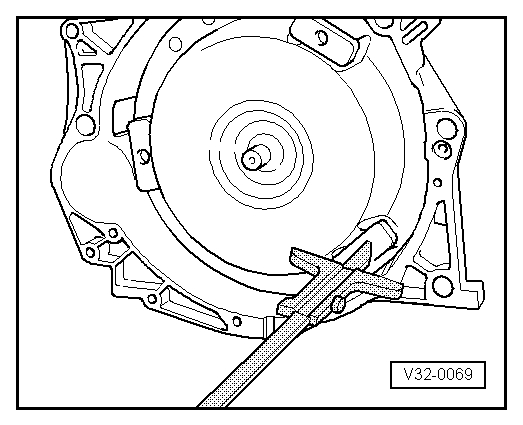
Depth gauge for vehicles with automatic gearbox 01V
Procedure
  Note
t  Renew self-locking nuts and bolts when performing assembly work.
t  Renew bolts which are tightened to a specified angle as well as oil seals and gaskets.
t  
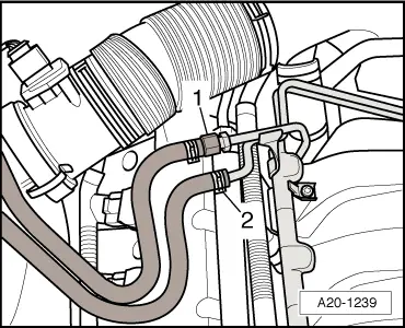
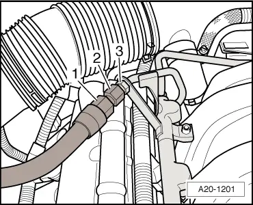
Secure all hose connections with the correct type of hose clips (same as original equipment) → Parts catalogue.
t  Secure the heat insulation sleeves in the original position when installing.
t  Fit all cable ties in the original positions when installing.
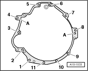
–  Check whether dowel sleeves for centring the engine/gearbox assembly are fitted in the cylinder block; install dowel sleeves if necessary.
–  Slip spacer plate over dowel sleeves.
Vehicles with manual gearbox:
–  Clean input shaft splines and (in the case of used clutch plates) the hub splines. Remove corrosion and apply only a very thin coating of grease for clutch plate splines -G 000 100- to the splines. Do not lubricate guide sleeve.
–  Check that the clutch plate is properly centralised (only necessary if you have carried out other work on the clutch).
–  Check clutch release bearing for wear and make sure that plastic ring is securely seated; renew clutch release bearing if necessary → Rep. Gr.30.
Vehicles with SAC pressure plate:
–  When fitting a new clutch plate together with a used pressure plate (self-adjusting clutch), the adjuster ring in the pressure plate has to be reset by turning it back as far as it will go. If this is not done, the pressure plate will operate with reduced clamping force, causing clutch slip → Rep. Gr.30.
  Note
t  If the clutch plate is not being replaced, it is not necessary to reset the adjuster ring.
t  New SAC pressure plates are already pre-set accordingly, and do not have to be reset.
Vehicles with multitronic gearbox:
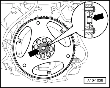
–  Clean input shaft splines and splines of damper unit on flywheel; remove corrosion and apply only a very thin coating of grease for clutch plate splines -G 000 100- to the splines. Remove any excess grease.
   
Vehicles with automatic gearbox 01V:
–  Secure drive plate with centralising disc -arrow- to crankshaft.
  A10-1036
If the torque converter has been correctly installed, the distance between the bottom contact surfaces at the threaded holes in the torque converter and the contact surface on the torque converter bell housing (with automatic gearbox 01V) is approx. 23 mm.
If the torque converter has not been completely inserted, this distance will be approx. 11 mm.
  Caution
If the torque converter is not installed correctly, the drive lugs of the torque converter and the ATF pump will be seriously damaged when the gearbox is joined to the engine.
  V32-0069
–  Before bringing engine and gearbox together, turn torque converter and drive plate on engine so that the holes for one securing bolt are in line with the opening for the starter motor -arrow-.
–  To secure torque converter on drive plate, use only new bolts of the correct type (same as original equipment) as specified in → Parts catalogue.
All vehicles:
–  Guide engine/gearbox assembly carefully into body.
–  Place engine down onto engine mountings.
  Caution
Before and during tightening of bolts on engine/gearbox flange, continually check that the torque converter behind the drive plate can be turned. If the converter cannot be turned, it must be assumed that it has not been installed correctly and the drive lugs of the ATF pump and consequently the gearbox will be damaged when the bolts are finally tightened.
–  Bolt gearbox to engine.
  A10-1022
–  Attach support -T10062- at tapped holes for torque reaction support and tighten to 20 Nm.
–  Using engine and gearbox jack -V.A.G 1383 A-, lift engine just far enough to fit bottom engine/gearbox securing bolts.
  Note
On vehicles with four-wheel drive, ensure that the front propshaft joint is not damaged when lifting the engine.
  A10-1262
–  Tighten bottom engine/gearbox securing bolts -arrows-.
–  Lower the engine back down.
  Note
t  Tightening torques apply only to lightly greased, oiled, phosphated or black-finished nuts and bolts.
t  Additional lubricant such as engine oil or gearbox oil may be used, but do not use lubricant containing graphite.
t  Do not use degreased parts.
t  Tolerance for tightening torques ± 15%.
  A34-0433
Engine/gearbox connecting bolts (manual gearbox)
  A10-1033
ItemBoltNm
1, 9, 10, 11M10x6045
2M10x15045
3M12x13065
4M12x8065
5, 6, 8M12x9065
7M10x10045
ADowel sleeves for centralising

   
Engine/gearbox connecting bolts (automatic gearbox 01J)
  A10-1033
ItemBoltNm
1, 10, 11M10x6045
2M10x9045
3M12x11065
4M12x8065
5, 6M12x9065
7M10x10045
8M12x7565
9M10x7045
ADowel sleeves for centralising

   
Engine/gearbox connecting bolts (automatic gearbox 01V)
  A10-1033
ItemBoltNm
1, 9, 10, 11M10x6045
2M10x9045
3M12x11065
4M12x8065
5, 6, 8M12x9065
7M10x10045
ADowel sleeves for centralising

Remaining installation steps are carried out in reverse sequence; note the following:
–  Align exhaust system so it is free of stress: vehicles with front-wheel drive → Chapter, vehicles with four-wheel drive → Chapter.
–  Install starter → Rep. Gr.27.
–  Install alternator → Rep. Gr.27.
–  Install air conditioner compressor → Rep. Gr.87.
–  Install poly V-belt → Chapter.
–  Install lock carrier with attachments → Rep. Gr.50.
–  Install bumper cover (front) → Rep. Gr.63.
   
Vehicles with return line:
–  Tighten union nut on fuel supply pipe -1- to 22 Nm.
–  Secure fuel return pipe -2- with the correct type of hose clip (same as original equipment) → Parts catalogue.
  A20-1239
Vehicles without return line:
–  Secure fuel hose at connection for fuel rail pipe. To do so, counterhold at hexagon flats -1- and -3- with open-end spanners and tighten union nut -2-: tightening torque 22 Nm.
Vehicles with multitronic gearbox 01J or automatic gearbox 01V:
–  Secure ATF lines → Rep. Gr.37.
All vehicles:
–  Electrical connections and routing → Current flow diagrams, Electrical fault finding and Fitting locations.
–  Observe notes on procedures required after connecting battery → Rep. Gr.27.
  Caution
Do not use a battery charger to boost starting. There is danger of damaging the vehicle's control units.
–  Install and adjust wiper arms → Rep. Gr.92.
–  Check oil level → Chapter.
–  Fill cooling system → Anchor.
  Note
t  Drained-off coolant may only be used again if the original cylinder head and cylinder block are re-installed.
t  Contaminated or dirty coolant must not be used again.
–  Top up power steering fluid and bleed steering system → Rep. Gr.48.
Vehicles with multitronic gearbox 01J or automatic gearbox 01V:
–  Check ATF level → Rep. Gr.37.
Tightening torques
  Note
t  Tightening torques apply only to lightly greased, oiled, phosphated or black-finished nuts and bolts.
t  Additional lubricant such as engine oil or gearbox oil may be used, but do not use lubricant containing graphite.
t  Do not use degreased parts.
t  Tolerance for tightening torques ± 15 %.
  A20-1201
ComponentNm
Bolts/nutsM610
 M820
 M1045
 M1265
Except for the following: 
Drive plate to torque converter85 1)
Torque reaction support to top section of sump40
Engine mounting to:Engine support23
 Subframe23
Drive shaft heat shield to gearbox23
Oil cooler to sump (top section)30
Pressure line for power steering to:Pressure hose40
Coolant pipe20
Air duct to intake manifold10
ATF hose to ATF pipe29
Front cross member to body55
l  1) Renew bolts.


Enginecrankshaft group, pistons > < Securing engine to assembly stand