audi Workshop Repair Guides

Audi Workshop Service and Repair Manuals

Checking hydraulic bucket tappets > < Renewing camshaft oil seals
Removing and installing camshafts and camshaft adjuster
Special tools and workshop equipment required
   
t  Puller -T10055-
  W00-0988
t  Assembly tool -T10029-
t  Electric drill with plastic brush attachment
t  Safety goggles
t  Sealant → Parts catalogue
Removing
–  Remove toothed belt → Chapter.
–  Remove camshaft sprockets on respective cylinder head.
–  Remove combination valve for secondary air system: left-side → Chapter, right-side → Chapter.
  W00-1195
Cylinder head (right-side):
–  Unplug electrical connector at Hall sender -G40--item 1- and at Hall sender 3 -G300--item 2-.
  A15-0714
–  Remove bolts -1- and take off bracket with idler roller.
–  Remove bolts -2- and take off toothed belt cover (rear right).
  A15-0705
Cylinder head (left-side):
–  Remove bolts -1- and -2- and take off toothed belt cover (rear left).
  A15-0706
Continuation for both sides:
–  Remove camshaft clamp -T40030- from camshafts.
–  Unscrew bolts -1 ... 6- and remove housing for camshaft control valves.
  A15-0717
–  Unscrew bolts -1 ... 6- and take off housing for Hall sender.
  A15-0718
–  Loosen bolts on retaining frame in the sequence shown by the numbers and then following the arrows.
  A15-0721
–  Press off retaining frame using M6 bolts -arrows-.
–  Carefully remove retaining frame.
–  Take out camshafts.
Installing
  Note
Renew gaskets and seals.
l  Crankshaft locked in position with locking pin -T40026-.
  WARNING
Wear safety goggles.
–  Remove sealant residue from cylinder head and retaining frame using a rotating plastic brush or similar.
–  Clean sealing surfaces; they must be free of oil and grease.
–  Lubricate running surfaces of camshafts.
  A15-0724
Cylinder head (left-side):
–  Position camshafts in cylinder head as illustrated.
l  The cams of No. 5 cylinder point downwards at equal angles -arrows-.
  A15-0722
Cylinder head (right-side):
–  Position camshaft in cylinder head as illustrated.
l  The cams of No. 3 cylinder point upwards at equal angles -arrows-.
  A15-0726
Continuation for both sides:
–  Cut off tube nozzle at front marking (nozzle approx. 1 mm Ø).
  A17-0081
–  Apply sealant bead to clean sealing surface of retaining frame, as shown in illustration.
l  The bead of sealant should be approx. 1.2 mm wide.
l  The sealant bead must be at least 5 mm away from the camshaft bearings at the points -1 ... 8- in the illustration.
l  Additionally apply a ring of sealant to the sealing surface around each spark plug hole -9 ... 11-.
  Note
t  The bead of sealant must be applied exactly according to these instructions, otherwise excess sealant can get into the camshaft bearings.
t  The retaining frame must be installed within 5 minutes after applying sealant.
  A15-0723
–  Fit retaining frame immediately and locate in position using locking pin -T40029-.
  Note
After installing the retaining frame, wait about 30 minutes for the sealant to dry.
  A15-0725
–  To start with, tighten bolts on retaining frame hand-tight: tighten uniformly in the sequence shown by the numbers, and then following the arrows.
l  The retaining frame should make contact with the cylinder head over the full surface.
–  Tighten bolts securing retaining frame to final torque (10 Nm).
  A15-0738
–  Pull mandrel -T40029- out of cylinder head and retaining frame using puller -T10055-.
  A15-0727
Cylinder head (left-side):
–  Attach camshaft clamp -T40030- to camshafts.
–  Expand camshaft clamp -T40030- by means of the threaded spindle (tightening torque max. 10 Nm) until it is seated with zero play.
  A13-0443
Cylinder head (right-side):
–  Install camshaft sprocket on exhaust camshaft.
–  Rotate exhaust camshaft -arrow 1- and inlet camshaft -arrow 2- 30° in direction of -arrows-.
  A15-0728
–  The cams -arrows- at No. 3 cylinder on inlet and exhaust camshafts must be positioned as shown in illustration.
  A13-0472
–  Attach camshaft clamp -T40030- to camshafts.
–  Remove camshaft sprocket from exhaust camshaft again.
  A13-0444
Continuation for both sides:
–  Install housing for Hall sender and tighten bolts -1 ... 6-.
  Note
  A15-0718
t  Depending on version, the piston rings on the camshaft adjusters are supplied with lugs at the ends.
t  Hook ends of piston rings together on this version.
  A15-0729
–  If necessary, hook ends of piston rings -arrows- together as illustrated.
  Note
  N38-0013
t  If camshaft oil seals are being renewed, they must be pried out using lever -T40017- before installing housing for camshaft control valves.
t  Installing camshaft oil seals → Chapter.
  A15-0736
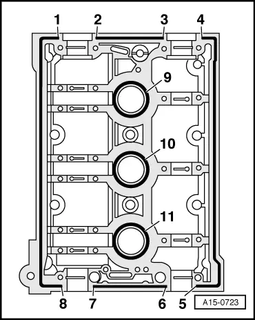
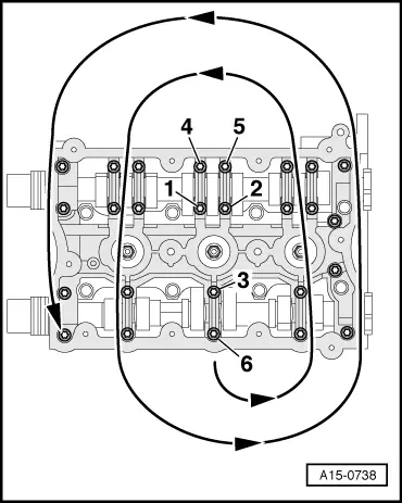
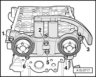
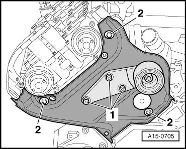
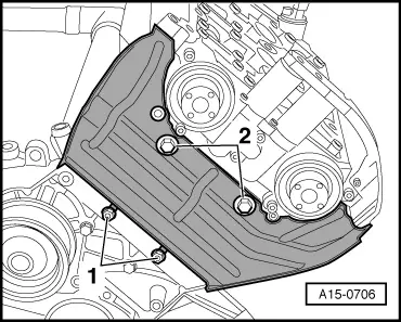
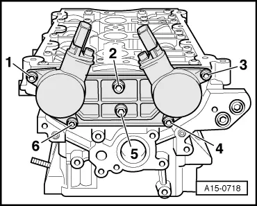
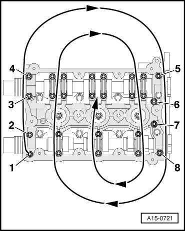
–  Install housing for camshaft control valves and tighten bolts -1 ... 6-.
Remaining installation steps are carried out in reverse sequence; note the following:
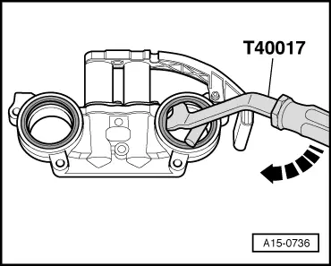
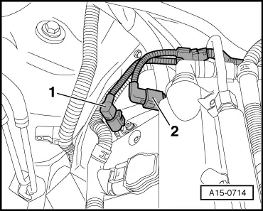
–  Install combination valve for secondary air system: left-side → Chapter, right-side → Chapter.
–  Install toothed belt (adjust valve timing) → Anchor.
  Note
t  After installing camshafts, wait for approx. 30 minutes before starting engine. Hydraulic valve compensation elements have to settle (otherwise valves will strike pistons).
t  After working on the valve gear, turn the engine carefully at least 2 rotations by hand to ensure that none of the valves make contact when the starter is operated.
Tightening torques
  A15-0717
ComponentNm
Retaining frame to cylinder head10
Hall sender housing to cylinder head10
Housing for camshaft control valves to cylinder head10
Toothed belt cover (rear) to cylinder head/ cylinder block10 1)
l  1) Renew bolts.


Checking hydraulic bucket tappets > < Renewing camshaft oil seals