audi Workshop Repair Guides

Audi Workshop Service and Repair Manuals

Cylinder block (gearbox end) > < Renewing crankshaft oil seal (pulley end)
Removing and installing sealing flange (front)
Special tools and workshop equipment required
   
t  Pin wrench -3212-
t  Electric drill with plastic brush attachment
t  Safety goggles
t  Sealant → Electronic parts catalogue
Removing
–  Drain off coolant → Chapter.
–  Move lock carrier to service position → Chapter.
–  Remove poly V-belt → Chapter.
–  Remove coolant pipe (right-side) → Chapter.
  W00-0462
–  Unbolt coolant pump pulley -arrows- (counterhold with pin wrench -3212-).
–  Remove vibration damper → Chapter.
  A13-0879
–  Pry off cover from idler roller for poly V-belt.
–  Unscrew bolt -arrow- and detach idler roller from front sealing flange.
  A13-0877
–  Detach noise insulation panel from sealing flange (front) -arrows-.
  A13-10170
–  Remove bolts.
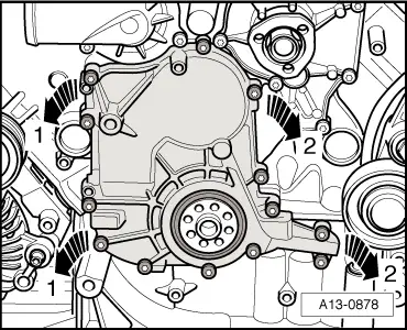
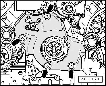
–  Pull off front sealing flange (right-side first -arrow 1-, then left-side -arrow 2-).
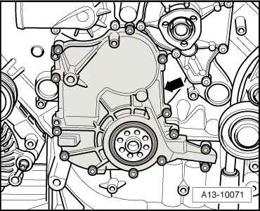
–  Drive out oil seal with sealing flange removed.
Installing
  Note
t  Renew gaskets, seals and O-rings.
t  Hose connections and hoses for charge air system must be free of oil and grease before assembly.
t  Secure all hose connections with the correct type of hose clips (same as original equipment) → Electronic parts catalogue.
t  
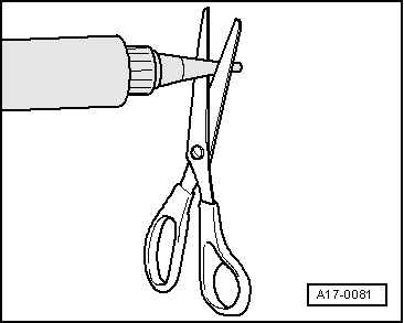
To ensure that the charge air hoses can be properly secured at their connections, spray rust remover onto the worm thread of used hose clips before installing.
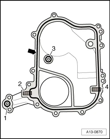
–  Remove old sealant from grooves in sealing flange and from sealing surfaces.
  A13-0878
  WARNING
Wear safety goggles.
–  Remove remaining sealant from sealing flange and cylinder block/sump (top section) with rotating plastic brush or similar.
–  Clean sealing surfaces; they must be free of oil and grease.
  A13-0590
–  Cut off tube nozzle at front marking (diameter of nozzle approx. 1.5 mm).
  A17-0081
–  Install sealing elements -2- and -4- and O-rings -1- and -3-.
–  Apply bead of sealant -arrow- onto clean sealing surface of front sealing flange as illustrated.
l  The bead of sealant must project 1.5 … 2.0 mm above the sealing surface.
  Note
t  The sealant bead must not be thicker than specified, otherwise excess sealant could enter the sump and clog the strainer in the oil pump.
t  The front sealing flange must be installed within 5 minutes after applying sealant.
  A13-0870
–  Tighten bolts securing front sealing flange -arrow- in diagonal sequence and in stages.
Remaining installation steps are carried out in reverse sequence; note the following:
–  Install crankshaft oil seal (pulley end) → Chapter.
–  Install vibration damper → Chapter.
–  Install coolant pipe (right-side) → Chapter.
–  Install poly V-belt → Chapter.
–  Install lock carrier with attachments → Rep. gr.50.
–  Install bumper cover (front) → Rep. gr.63.
–  Fill cooling system → Anchor.
Tightening torques
  A13-10071
ComponentNm
Front sealing flange to cylinder block9
Noise insulation to engine9
Idler roller to sealing flange23
Poly V-belt pulley to coolant pump23
Hose clipsWidth 9 mm3
Width 13 mm5.5


Cylinder block (gearbox end) > < Renewing crankshaft oil seal (pulley end)