audi Workshop Repair Guides

Audi Workshop Service and Repair Manuals

Removing and installing intermediate flange on vehicles with 2.7 ltr. engine > < Removing and installing turbocharger on vehicles with 2.7 ltr. engine
Removing and installing turbocharger 1 control unitJ724 - vehicles with 2.7 ltr. engine
Removing and installing turbocharger 1 control unit -J724- - vehicles with 2.7 ltr. engine
Special tools and workshop equipment required
t  Tester -VAS 6395/1-
t  Connection lead -VAS 6395/2-
t  Stop plate -VAS 6395/3-
   
Removing
Proceed as follows:
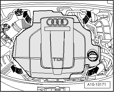
–  Carefully pull engine cover panel off four retaining pins one after the other -arrows-.
  A10-10171
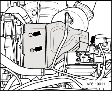
–  Remove bolts -arrows- and detach heat shield for turbocharger.
  Note
The bottom bolt -right arrow- does not have to be completely removed.
  A26-10011
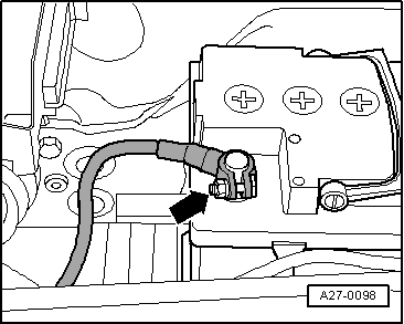
–  Connect tester -VAS 6395/1- with connecting wire -VAS 6395/2- to positive battery terminal -arrow- and negative battery terminal.
  A27-0098
Checking software version of tester -VAS 6395/1-:
  Caution
Risk of damage to turbocharger 1 control unit -J724-.
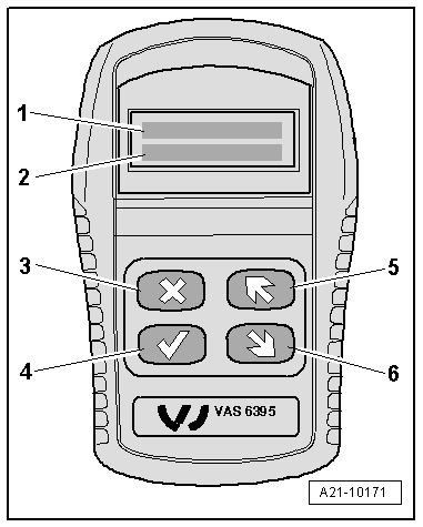
Before continuing, check whether the correct software version is loaded in the tester -VAS 6395/1-. To do so, proceed as follows:
Display on -VAS 6395/1- (2 seconds after connecting to power supply) if correct software version is loaded:
1 - > 1. START
2 -  2. NEXT [>]
  Note
t  If the following appears on the display, an incorrect software version has been loaded:
t  1. >TEST
t  2. LEARN
t  If this is the case, download the correct software version from the „Audi ServiceNet“ under „Workshop Equipment“.
  A21-10171
Continuation of procedure:
–  Unplug electrical connector for turbocharger 1 control unit -J724-.
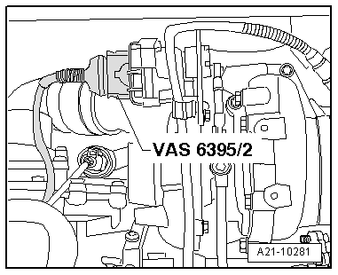
–  Connect connection lead -VAS 6395/2- to turbocharger 1 control unit -J724- and to tester -VAS 6395/1-.
  A21-10281
Display on -VAS 6395/1-:
1 - > 1. START
2 -  2. NEXT [>]
–  To continue, press v button -item 4-.
l  The tester -VAS 6395/1- runs through the adjustment range of the turbocharger 1 control unit -J724- and checks that the end positions are reached; display indicates „CHECK“.
  A21-10171
Display on -VAS 6395/1-:
1 - 
2 - [OK]
  Note
t  If the display indicates „[OK]“, the adjustment range of the turbocharger 1 control unit -J724- is stored.
t  If the display shows „FAULT [OK]“, tap gently several times on the housing of turbocharger 1 control unit -J724- with the handle of a screwdriver and repeat the check by pressing v button -item 4-.
  A21-10171
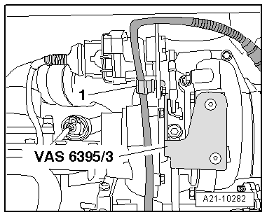
–  Unclip retaining clip -1- and move electrical wire clear.
–  Secure stop plate -VAS 6395/3- with bolts for heat shield. Tightening torque: 8 Nm.
  Caution
The stop plate -VAS 6395/3- must not be loosened until the work sequence has been completed.
  A21-10282
–  To continue, press v button -item 4-.
l  The turbocharger 1 control unit -J724- moves back and forth between the stops several times to determine the voltage value.
l  Then the turbocharger 1 control unit -J724- moves into installation position.
–  While the voltage value is being determined, keep tapping gently on the housing of turbocharger 1 control unit -J724- until the display indicates the following:
Display on -VAS 6395/1-:
1 - X.XXX V
2 - [↑][↓][OK]
–  Note voltage value.
l  Specification: 3.3 ... 3.7 V
  Note
If the display indicates „FAULT [OK]“ or the voltage is less than 3.3 V or greater than 3.7 V, unplug tester -VAS 6395/1- and repeat the complete procedure → Anchor.
  A21-10171
Display on -VAS 6395/1-:
1 - X.XXX V
2 - [↑][↓][OK]
–  By pressing buttons -item 5- and -item 6-, adjust turbocharger 1 control unit -J724- so that coupling rod can be accessed easily for removal.
  A21-10171
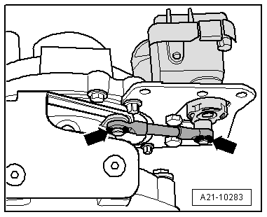
–  Unclip circlips -arrows- and dispose of them, detach coupling rod.
  A21-10283
Display on -VAS 6395/1-:
1 - X.XXX V
2 - [↑][↓][OK]
–  By pressing buttons -item 5- and -item 6-, adjust turbocharger 1 control unit -J724- so that bolts for -J724- can be accessed easily.
  A21-10171
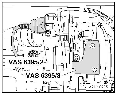
–  Disconnect connection lead -VAS 6395/2- from turbocharger 1 control unit -J724-.
  Caution
Power supply for tester -VAS 6395/1- must remain connected.
  A21-10285
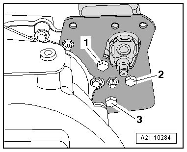
–  Remove bolts -1, 2, 3- and dispose of them.
–  Remove old turbocharger 1 control unit -J724- and dispose of it.
  Caution
Check that the three insulating washers are fitted between turbocharger 1 control unit -J724- and the bracket.
–  Install new turbocharger 1 control unit -J724- in reverse sequence of removal.
–  Fit new bolts as follows:
1 - M6x15 with tapered shank
2 - M6x15 with tapered shank
3 - M6x15
–  Initially hand-tighten bolts.
l  Turbocharger 1 control unit -J724- must rest on retaining plate so there is no play; it must still be possible to move control unit by hand.
  A21-10284
–  Connect connection lead -VAS 6395/2- to new turbocharger 1 control unit -J724-.
  A21-10285
–  To continue, press v button -item 4-.
Display on -VAS 6395/1-:
1 - > 1. START
2 - 2. NEXT [>]
–  Select menu item „NEXT“ with button -item 6-.
  A21-10171
–  To continue, press v button -item 4-.
Display on -VAS 6395/1-:
1 - X.XXX V
2 - [OK]
  Note
t  If the display indicates „CHECK“, the adjustment range of the new turbocharger 1 control unit -J724- must be checked → Anchor.
t  If the display indicates „FAULT“, the new turbocharger 1 control unit -J724- must be renewed for a second time.
  A21-10171
–  To continue, press v button -item 4-.
l  Turbocharger 1 control unit -J724- runs through the adjustment range.
Display on -VAS 6395/1-:
1 - 
2 - [OK]
  A21-10171
–  To continue, press v button -item 4-.
Display on -VAS 6395/1-:
1 - X.XXX V
2 - [OK]
l  Turbocharger 1 control unit -J724- moves into installation position.
  A21-10171
–  Insert coupling rod.
l  Installation position: The thicker eyelet is fitted onto the shaft of turbocharger 1 control unit -J724-.
–  Fit circlips -arrows-.
l  The circlips must engage audibly.
  A21-10283
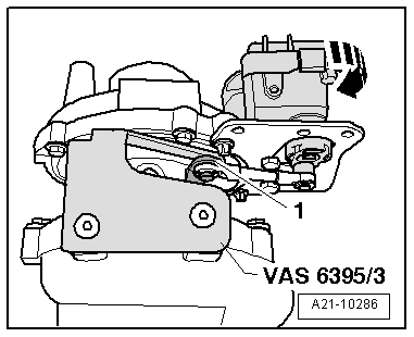
–  Press turbocharger 1 control unit -J724- towards the rear without applying force -arrow- until lever -1- rests lightly on stop plate -VAS 6395/3-.
–  Hold -J724- in this position.
  A21-10286
–  Tighten bolts -1, 2, 3- to 5 Nm.
  A21-10284
–  To continue, press v button -item 4-.
l  Turbocharger 1 control unit -J724- moves back and forth between the stops several times and is adjusted to the voltage value determined with the first measurement.
Display on -VAS 6395/1-:
1 - X.XXX V (voltage determined with first measurement)
2 - [OK]
  Note
t  If [OK] is indicated on display, terminate adjustment → Anchor.
t  If „CHECK“ is indicated on display, proceed as follows.
  A21-10171
Procedure if display indicates „CHECK“:
Display on -VAS 6395/1-:
1 - [<<<]
2 - CHECK
Or
1 - [>>>]
2 - CHECK
  A21-10171
–  Loosen bolts -1, 2, 3- until turbocharger 1 control unit -J724- can just be moved by applying light force in the direction stated:
l  If display indicates [<<<], move -J724- slightly in direction of travel.
l  If display indicates [>>>], move -J724- slightly towards rear of vehicle.
–  Tighten bolts -1, 2, 3- to 5 Nm.
  A21-10284
–  To continue, press v button -item 4-.
l  Turbocharger 1 control unit -J724- again moves back and forth between the stops several times and is adjusted to the voltage value determined with the first measurement.
Display on -VAS 6395/1-:
1 - X.XXX V (voltage determined with first measurement)
2 - [OK]
  A21-10171
Terminating adjustment:
–  Tighten bolts -1, 2, 3- to 10 Nm.
  A21-10284
–  To continue, press v button -item 4-.
Display on -VAS 6395/1-:
1 - > 1. X.XXX V
2 -  2. [OK]
  A21-10171
–  Remove stop plate -VAS 6395/3-.
–  Secure electrical wiring with retaining clip -1-.
  A21-10282
–  To continue, press v button -item 4-.
l  Turbocharger 1 control unit -J724- moves to end positions.
  Note
If the display indicates „FAULT“, the new turbocharger 1 control unit -J724- must be renewed → Anchor.
Display on -VAS 6395/1-:
1 - 
2 - [OK]
l  Adjustment is completed.
–  Unplug electrical connectors for tester -VAS 6395/1-.
Assemble in reverse order.
  A21-10171

Removing and installing intermediate flange on vehicles with 2.7 ltr. engine > < Removing and installing turbocharger on vehicles with 2.7 ltr. engine