audi Workshop Repair Guides

Audi Workshop Service and Repair Manuals

Assembly mountings > < Securing engine to engine and gearbox support
Installing engine
Installing engine
  Note
t  Renew self-locking nuts and bolts when performing assembly work.
t  Renew bolts which are tightened to a specified angle as well as seals, gaskets and O-rings.
t  Secure all hose connections with the correct type of hose clips (same as original equipment) → Electronic parts catalogue.
t  Fit all heat shields and heat insulation sleeves in the original positions when installing.
t  Fit all cable ties in the original positions when installing.
–  When fitting a new clutch plate together with a used pressure plate (self-adjusting clutch), the adjuster ring in the pressure plate has to be reset by turning it back as far as it will go. If this is not done, the pressure plate will operate with reduced clamping force, causing clutch slip → Rep. Gr.30.
  Note
t  If the clutch plate is not being replaced, it is not necessary to reset the adjuster ring.
t  New SAC pressure plates are already pre-set accordingly, and do not have to be reset.
–  Clean input shaft splines and (in the case of used clutch plates) the hub splines. Remove corrosion and apply only a very thin coating of grease -G 000 100- to the splines. Do not lubricate guide sleeve.
–  Check that the clutch plate is properly centralised (only necessary if you have carried out other work on the clutch).
–  Check clutch release bearing for wear and make sure that plastic ring is securely seated → Rep. Gr.30.
–  Install engine supports (left and right) → Chapter.
   
–  Check whether dowel sleeves -A- for centring engine and gearbox are fitted in cylinder block; install missing dowel sleeves.
–  Press intermediate plate between engine and gearbox onto dowel sleeves.
–  Bolt gearbox to engine.
  Note
t  Tightening torques apply only to lightly greased, oiled, phosphated or black-finished nuts and bolts.
t  Additional lubricants such as engine or gearbox oil may be used, but do not use lubricants containing graphite.
t  Do not use degreased parts.
t  Tolerance for tightening torques ± 15 %.
  A10-1641
Securing engine to gearbox
  A10-1641
ItemBoltNm
1, 2M12x12065
3M12x11065
4, 5M12x10565
6M12x13065
7M12x17065
8, 9, 10M10x6045
ADowel sleeves for centralising

Remaining installation steps are carried out in reverse sequence; note the following:
–  Install exhaust manifolds: left-side → Chapter, right-side → Chapter.
–  Install front exhaust pipes with starter and main catalytic converter: left-side → Chapter, right-side → Chapter.
–  The threaded holes in the flange shaft for the propshaft on the gearbox must be cleaned of remaining locking fluid with a thread tap before assembling.
   
–  Screw down spindles of support elements on left side of engine/gearbox assembly.
–  Unscrew both base plates for support elements (left-side) at scissor-type assembly platform -VAS 6131 A-.
  A10-10225
–  Screw down spindles of support elements on right side of engine/gearbox assembly.
–  Unscrew both base plates for support elements (right-side) at scissor-type assembly platform -VAS 6131 A-.
  Note
The mounting points for engine (front) and tunnel cross member remain unchanged.
  A10-10226
–  Set up scissor-type assembly platform -VAS 6131 A- with support set for Audi -VAS 6131/10- as follows:
  A10-1764
Platform coordinatesParts from support set for Audi -VAS 6131/10-
B4 1)/10-1/10-4/10-5/10-12
G3 1)/10-1/10-4/10-5/10-6
B10/10-1/10-2/10-5/10-8 2)
G10/10-1/10-2/10-5/10-8 2)
C14 1)/10-1/10-3/10-5/10-7
E14 1)/10-1/10-3/10-5/10-7
l  1) Support elements remain unchanged.
l  2) Secure support elements only after installing the subframe.

   
–  Fit subframe onto the two support elements -VAS 6131/10-8-.
–  Screw up the spindles for support elements on both sides.
–  Tighten base plates for support elements to 20 Nm on scissor-type assembly platform -VAS 6131 A-.
–  Carefully guide engine/gearbox assembly together with subframe into the body from below using scissor-type assembly platform -VAS 6131 A-.
  A10-10133
–  Raise the engine/gearbox assembly using scissor-type assembly platform -VAS 6131 A- until the distance -a- is reached.
l  Dimension -a- = max. 100 mm.
  A10-10106
–  Secure coolant hose -arrow- to rear coolant pipe (hose leads to heat exchanger for heater).
  A19-10200
–  Secure slave cylinder with new bolt -arrow-; procedure → Rep. Gr.30.
–  Install selector mechanism → Rep. Gr.34.
  A34-0641
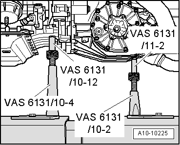
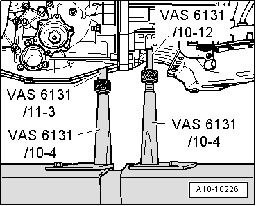
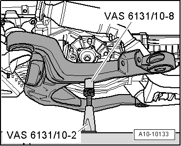
–  Raise subframe via scissor-type assembly platform -VAS 6131 A- until subframe makes contact with body.
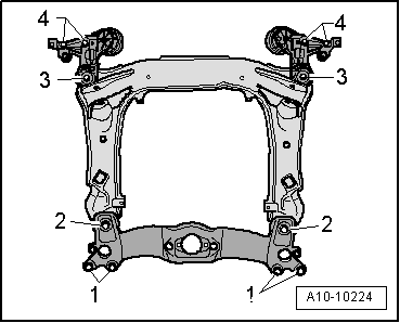
–  Adjust the subframe, consoles for engine mountings and tunnel cross member according to the markings made on the longitudinal members during removal.
–  Only tighten bolts for subframe, consoles for engine mountings and tunnel cross member to the specified torque (do not turn further); tighten bolts to final setting only after performing wheel alignment check → Rep. Gr.40.
  WARNING
The vehicle must not be driven at this stage.
–  Install drive shafts → Rep. Gr.40.
–  Install guide links, track control links and suspension struts → Rep. Gr.40.
–  Install propshaft → Rear final drive 01R; Rep. Gr.39.
–  Align exhaust system so it is free of stress → Chapter.
–  Install hydraulic pressure line for power steering → Rep. Gr.48.
–  Secure fuel supply line to fuel rail → Rep. Gr.20.
–  Install refrigerant lines → Rep. Gr.87.
–  Install anti-roll bar → Rep. Gr.40.
–  Install torque reaction support → Chapter.
–  Install lock carrier with attachments → Rep. Gr.50.
–  Install bumper cover (front) → Rep. Gr.63.
–  Electrical connections and routing → Current flow diagrams, Electrical fault finding and Fitting locations.
–  Observe notes on procedures required after connecting battery → Rep. Gr.27.
  Caution
Do not use a battery charger to boost starting. There is danger of damaging the vehicle's control units.
–  Install and adjust wiper arms → Rep. Gr.92.
–  Fill up with engine oil and check oil level → Booklet803 or → Booklet805.
–  Before starting engine, top up hydraulic fluid in power steering reservoir → Rep. Gr.48.
  Note
The power steering pump must not be run when dry.
–  Fill cooling system → Anchor.
  Note
t  Drained-off coolant may only be used again if the original cylinder head and cylinder block are re-installed.
t  Contaminated or dirty coolant must not be used again.
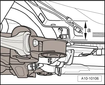
–  Charge the refrigerant system → Air conditioner system - with refrigerant R134a.
–  Adjust subframe and the two consoles for engine mountings → Rep. Gr.40.
–  Fit front wheels and perform wheel alignment → Rep. Gr.44.
  WARNING
Tighten bolts for subframe to final setting after performing wheel alignment check.
–  Check headlight adjustment → Booklet803 or → Booklet805.
Tightening torques
  Note
t  Tightening torques apply only to lightly greased, oiled, phosphated or black-finished nuts and bolts.
t  Additional lubricants such as engine or gearbox oil may be used, but do not use lubricants containing graphite.
t  Do not use degreased parts.
t  Tolerance for tightening torques ± 15 %.
  A10-10224
ComponentNm
Bolts/nutsM69
 M820
 M1040
 M1265
Except for the following: 
Drive shaft heat shield to gearbox23
Engine oil cooler pipes to sump (top section)8
l  1) Apply locking fluid when installing; refer to → Electronic parts catalogue for locking fluid.
l  2) Renew bolt.


Assembly mountings > < Securing engine to engine and gearbox support