
A4 Cabriolet Mk2
| Removing timing chains from camshafts - vehicles from 03.2007 onwards |

| Special tools and workshop equipment required |
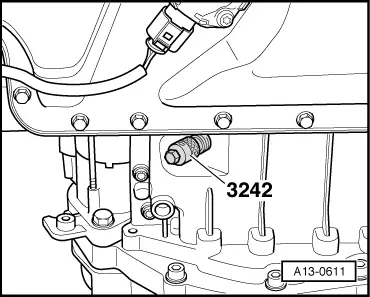
| t | Locking pin -3242- |
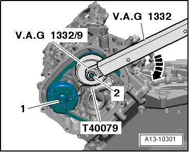
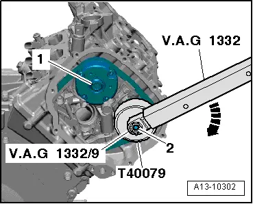
| t | Torque wrench -V.A.G 1332- |
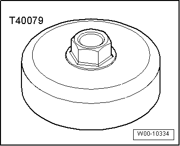
| t | Socket -V.A.G 1332/9- |
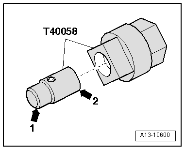
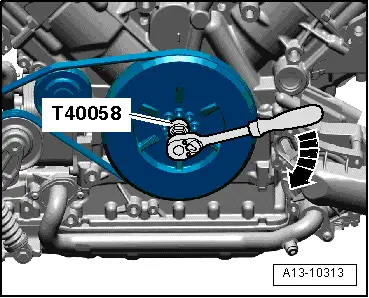
| t | Adapter -T40058- |
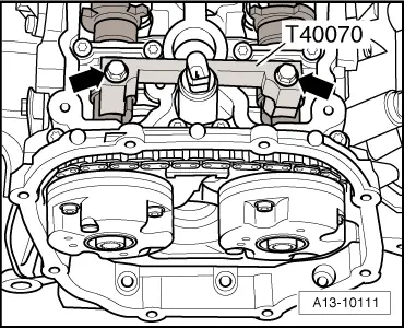
| t | 2x Camshaft clamp -T40070- |
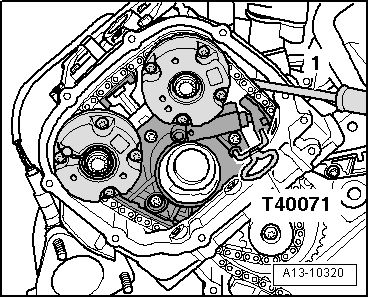
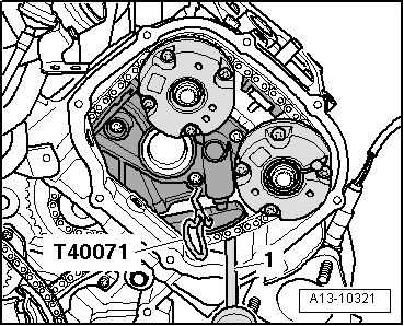
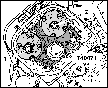
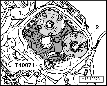
| t | 2x Locking pin -T40071- |
|
|
 Note
Note
|
|
|
|
|
|
|
|
|
|
|
|
Note
|
|
Note
|
|
|
|
 Caution
|
|
|
|
|
|
|
|
|
|
|
|
|
|
|
|
|
|
|
|
|
|
|
|
Note
|
|
|
|
|
|
|
|