audi Workshop Repair Guides

Audi Workshop Service and Repair Manuals

Removing and installing engine control unit 2 J624 > < Wiring and component check with test box V.A.G 1598/42
Removing and installing engine control unitJ623
Removing and installing engine control unit -J623-
Special tools and workshop equipment required
   
t  Hot air blower (220 V/ 50 Hz) -VAS 1978/14--item 1- with nozzle attachment -2- from wiring harness repair set -VAS 1978-
t  Vice-grip pliers -3- (commercially available)
  Note
  A24-0475
t  The engine control unit -1- is bolted to the protective housing -5-. To make it more difficult to unscrew the shear bolts -4- for locking plate -2-, their threads have been coated with locking fluid.
t  The protective housing has to be removed before the connectors can be unplugged from the engine control unit (e.g. to connect the test box or renew the engine control unit).
Removing
–  When renewing engine control unit, select diagnosis object “Renew engine control unit” in “Guided Functions” mode → Vehicle diagnosis, testing and information system VAS 5051.
–  Switch off ignition and remove ignition key.
  A24-0593
–  Detach rubber seal from plenum chamber cover in direction of -arrow-.
–  Detach plenum chamber cover -1- towards the front.
  A27-0088
–  Lever off both cover caps -3- with a screwdriver.
–  Loosen hexagon nuts -4- several turns.
–  Loosen wiper arms -2- from wiper shafts by tilting slightly.
–  Completely remove hexagon nuts and take off wiper arms.
  Note
Use a normal commercial puller if the wiper arm cannot be removed from the wiper shaft.
–  Pull off retaining clips -1- and detach cowl panel grille -5-.
  A20-0833
–  Remove cover for electronics box in plenum chamber -arrows-.
  A10-0996
–  Use a screwdriver to carefully lever out the retaining strap -arrow- and remove the engine control unit from the electronics box.
  Note
The engine control unit remains connected to the wiring harness.
  Caution
The following procedure must be followed exactly to prevent any damage (burning) to wiring, connectors, insulation and control units. Observe operating instructions for hot air blower.
  A10-0997
–  Select settings on hot-air blower as shown in illustration, i.e. set temperature potentiometer -2- to max. heat output and two-stage air flow switch -3- to position “3”.
  Note
Then use hot air blower to heat threaded holes in protective housing into which shear bolts have been screwed. This reduces the inhibiting action of the locking fluid on the shear bolt threads and makes it easier to unscrew these bolts.
  WARNING
Parts of the protective housing will become very hot as a result of heating the shear bolts. Take care to avoid burns. Try to ensure that only the thread is heated and none of the nearby components. These should be covered if necessary.
  A24-0476
–  Carry out the following operations on the two shear bolts -4- in turn.
  A24-0593
–  Place the nozzle of the hot air blower close to the shear bolt on the protective housing.
–  Switch on the hot air blower and heat the bolt for approximately 20 ... 25 seconds.
  A24-0594
–  Unscrew shear bolts using vice-grip pliers -arrow-.
  Note
  A24-0595
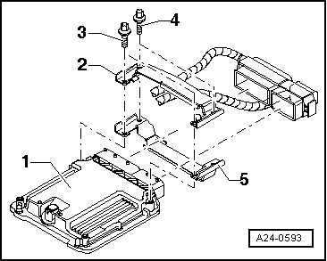
The threads of the two shear bolts -3- which are screwed into the engine control unit are not secured with locking fluid. Do not apply heat to the threads in the control unit housing; this is not necessary and would cause overheating of the control unit.
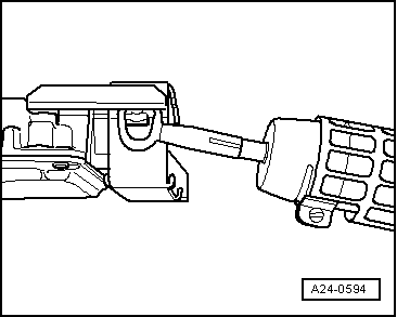
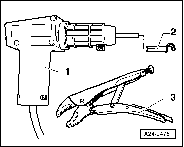
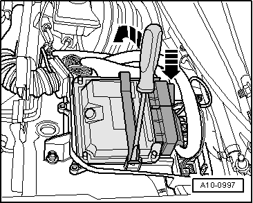
–  Unscrew the two shear bolts -3-.
–  Release locking plate -2- for control unit connectors.
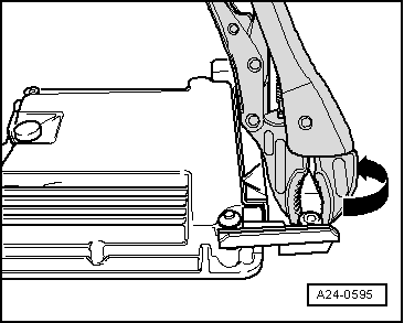
–  Release retaining tabs and unplug connectors from engine control unit.
  Note
When the connectors are disconnected from the engine control unit, the learnt values are erased but the contents of the fault memory remain intact.
Installing
Installation is carried out in the reverse order; note the following:
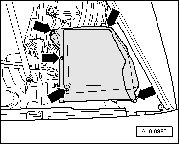
–  Protective housing must be fitted back on engine control unit.
–  Clean threaded holes for shear bolts to remove any residue from locking fluid. This can be done using a thread tap.
–  Use new shear bolts.
After installing a new engine control unit, the following operations must be performed:
–  Activate engine control unit via vehicle diagnostic, testing and information system -VAS 5051B- in “Guided Functions” mode, “Replace engine control unit”.
  A24-0593

Removing and installing engine control unit 2 J624 > < Wiring and component check with test box V.A.G 1598/42