audi Workshop Repair Guides

Audi Workshop Service and Repair Manuals

Suction-jet pump: operation > < Checking fuel gauge sender 2 G169
Removing and installing fuel gauge sender 2G169
Removing and installing fuel gauge sender 2 -G169-
Special tools and workshop equipment required
   
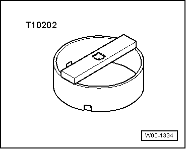
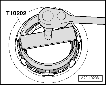
t  Special wrench -T10202-
Removing
Observe safety precautions → Chapter.
Observe rules for cleanliness → Chapter.
l  The fuel tank must not be more than 1/4 full when removing fuel gauge sender 2 -G169-. Drain the tank if necessary. Procedure → Chapter.
–  Briefly open filler cap for fuel tank and close again.
  W00-1334
–  Remove rear seat bench → Rep. Gr.72.
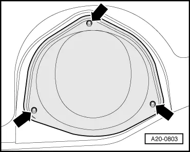
–  Detach cover for flange (left-side) -arrows-.
  A20-0803
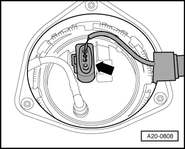
–  Unplug electrical connector -arrow- at flange (left side of vehicle).
  WARNING
t  The fuel system is pressurised. Before opening the system place a clean cloth around the connection. Then release pressure by carefully loosening the connection.
t  In extreme cases the fuel lines and the fuel can reach a temperature of 100 °C on vehicles with unit injector engine. Allow the fuel to cool down before disconnecting the lines - danger of scalding.
t  Wear protective gloves.
t  Wear safety goggles.
  A20-0808
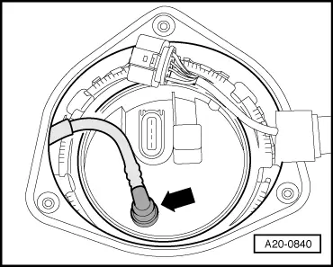
–  Disconnect fuel line -arrow- from flange (left side of vehicle) by pressing release tab.
  A20-0840
  Caution
The fuel tank must not be more than 1/4 full when removing the fuel gauge sender 2 -G169-. Otherwise a large amount of fuel will escape.
–  Unscrew locking ring using wrench -T10202- (left side of vehicle).
  A20-10236
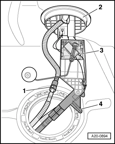
–  Carefully pull flange with fuel gauge sender 2 -G169- and seal just slightly out of opening in fuel tank.
–  First pull fuel line -1- out of fuel tank.
–  Swivel flange -2- with fuel gauge sender 2 -G169--item 3- and suction-jet pump -4- out of fuel tank opening.
  Note
When removing, make sure you do not bend float arm of fuel gauge sender 2 -G169-.
–  Unclip suction-jet pump from flange with fuel gauge sender 2 -G169-.
  A20-0894
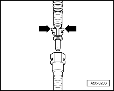
–  Press release tabs -arrows- and disconnect fuel hose from connector.
–  Remove flange with fuel gauge sender 2 -G169-.
Installing
Installation is carried out in the reverse order; note the following:
  Note
t  Renew seal.
t  When installing, make sure you do not bend float arm of fuel gauge sender 2 -G169-.
t  Ensure that fuel hose is securely connected.
  A20-0203
–  Install new seal for flange (seal must be installed dry).
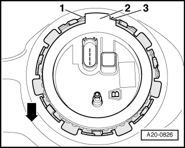
–  Move flange to installation position.
l  Lug -2- on flange must be between tabs -1- and -3- on fuel tank.
  Note
The -arrow- points in direction of travel.
  A20-0826
–  Tighten locking ring.
Tightening torque
  A20-10236
ComponentNm
Locking ring for flange of fuel gauge sender 2 -G169-145


Suction-jet pump: operation > < Checking fuel gauge sender 2 G169