
A4 Cabriolet Mk2
| Fuel delivery unit and fuel gauge sender - exploded view of components |
 Note
Note| Illustration shows fuel delivery unit on vehicles with 6-cylinder engine. |
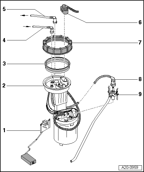
| 1 - | Fuel gauge sender -G- |
| q | Checking resistance values → Chapter |
| q | Removing and installing → Chapter |
| 2 - | Fuel delivery unit |
| q | Checking fuel pump (electrical test) → Chapter |
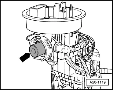
| q | On vehicles with 4-cylinder FSI engine with integrated fuel pressure regulator → Fig. |
| q | Checking residual pressure → Rep. Gr.24 |
| q | Removing and installing → Chapter |
| q | Put at least 5 litres of fuel into tank after installing |
| 3 - | Seal |
| q | Renew |
| q | Install dry |
| 4 - | Fuel return pipe |
| q | Mark before removing |
| q | Press release tab on pipe connector to disconnect |
| q | Do not kink |
| q | Note direction of arrow (fuel supply or fuel return system) on flange when installing |
| q | Clip onto fuel tank |
| 5 - | Fuel supply pipe |
| q | Mark before removing |
| q | Press release tab on pipe connector to disconnect |
| q | Do not kink |
| q | Note direction of arrow (fuel supply or fuel return system) on flange when installing |
| q | Clip onto fuel tank |
| 6 - | Electrical connector |
| q | For fuel gauge sender -G- |
| q | For fuel system pressurisation pump -G6- |
| 7 - | Union nut, 80 Nm |
| q | Remove and install with union nut tool -3217- |
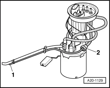
| 8 - | Supply pipe for suction-jet pump |
| q | Press release tab on pipe connector to disconnect |
| 9 - | Suction-jet pump |
| q | On vehicles with auxiliary heater (from approx. 02.2003 onwards) suction pipe for auxiliary heater runs along suction pipe for suction-jet pump → Fig. |
|
|