
A4 Cabriolet Mk2
| Fuel delivery unit and fuel gauge senders - exploded view of components |
| Part 1 (right chamber) |
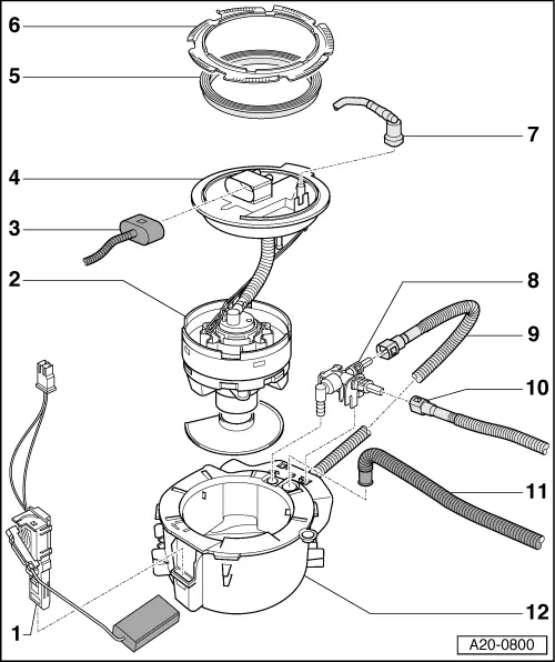
| 1 - | Fuel gauge sender -G- |
| q | Clipped onto baffle housing in fuel tank |
| q | Checking resistance values → Chapter |
| q | Removing and installing → Chapter |
| 2 - | Fuel delivery unit |
| q | Different versions are available; allocation → Parts catalogue |
| q | Can only be renewed together with flange |
| q | Checking fuel pump (electrical test) → Chapter |
| q | Checking residual pressure → Rep. Gr.24 |
| q | Removing and installing → Chapter |
| q | Put at least 5 litres of fuel into tank after installing |
| 3 - | Electrical connector |
| q | For fuel gauge sender -G- |
| q | For fuel system pressurisation pump -G6- |
| 4 - | Flange |
| q | For fuel delivery unit |
| q | Cannot be renewed separately |
| q | Installation position → Anchor |
| 5 - | Seal |
| q | Renew |
| q | Install dry |
| 6 - | Locking ring |
| q | Remove and install using wrench -T10202- |
| q | Tighten to 145 Nm |
| 7 - | Fuel pipe |
| q | To fuel filter |
| q | Press release tab on pipe connector to disconnect |
| q | Do not kink |
| q | Clip onto fuel tank |
| 8 - | Connecting piece |
| q | Different versions are available; allocation → Parts catalogue |
| q | Clipped into baffle housing with retaining hooks |
| q | To remove, press towards the right to release retaining hooks and lift out |
| 9 - | Supply pipe for suction-jet pump |
| q | To suction-jet pump in baffle housing |
| 10 - | Supply pipe for suction-jet pump |
| q | From flange (left-side) |
| 11 - | Fuel supply pipe |
| q | From suction-jet pump (left-side) |
| 12 - | Baffle housing |
| q | With suction-jet pump |
| Part 2 (left chamber) |

| 1 - | Baffle housing |
| q | With suction-jet pump |
| 2 - | Connecting piece |
| q | Different versions are available; allocation → Parts catalogue |
| q | Clipped into baffle housing with retaining hooks |
| q | To remove, press towards the right to release retaining hooks and lift out |
| 3 - | Supply pipe for suction-jet pump |
| q | To suction-jet pump in baffle housing |
| 4 - | Supply pipe for suction-jet pump |
| q | From flange (left-side) |
| 5 - | Fuel pipe |
| q | From engine or fuel filter |
| q | Press release tab on pipe connector to disconnect |
| q | Do not kink |
| q | Clip onto fuel tank |
| 6 - | Seal |
| q | Renew |
| q | Install dry |
| 7 - | Locking ring |
| q | Remove and install using wrench -T10202- |
| q | Tighten to 145 Nm |
| 8 - | Electrical connector |
| q | For fuel gauge sender 2 -G169- |
| 9 - | Flange |
| q | Only available together with → Item. |
| q | Installation position → Anchor |
| 10 - | Fuel gauge sender 2 -G169- |
| q | Only available together with → Item. |
| q | Checking resistance values → Chapter |
| q | Removing and installing → Chapter |
| 11 - | Suction-jet pump |
| q | With pipes |
| q | Different versions are available; allocation → Parts catalogue |
| q | Secured on flange |
| q | Function → Chapter |
| q | Removing and installing → Chapter |
| 12 - | Fuel supply pipe |
| q | From suction-jet pump (left-side) |