
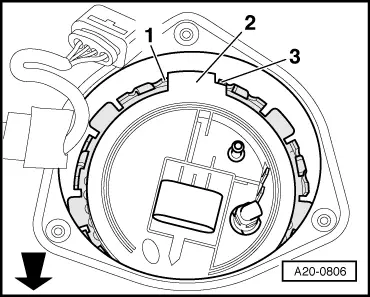
Removing and installing fuel delivery unit for Audi A4 Cabriolet Mk2
|
|
|
|
|
|
|
 Caution
|
|
|
|
|
|
 WARNING
|
|
|
|
 Note
Note |
|
|
|
|
|
|
|
|
|
|
|
Note
|
|
|
|
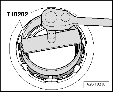
| Component | Nm | |
| Locking ring for fuel delivery unit | 145 | |