audi Workshop Repair Guides

Audi Workshop Service and Repair Manuals

Dismantling and assembling air cleaner > < Technical data
Motronic Direct Injection and Ignition System (4-Cyl.)
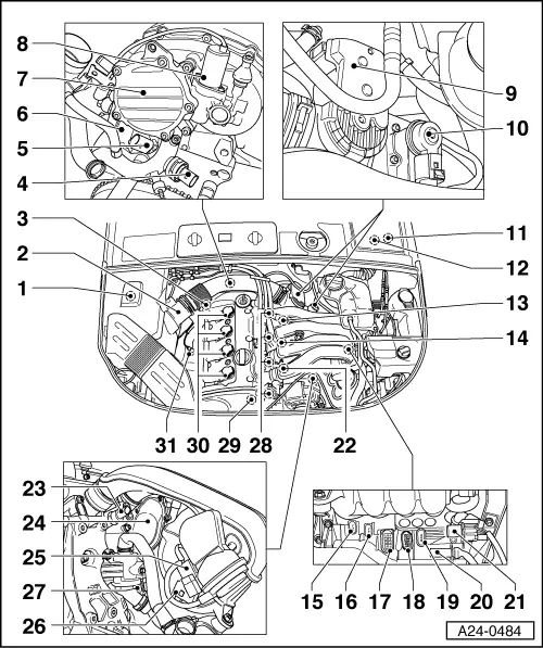
Servicing injection system
Exploded view of fitting locations
 
A24-0484

Components A to C are not shown in the exploded view.

  •     A -    Diagnostic connector
    • ◆ In driver's knee restraint
  •     B -    Fuel pump relay
    • ◆ In micro central electrics behind driver's storage compartment, relay position 4
  •     C -    "EPC" warning lamp
    • ◆ In dash panel insert
 
A24-0484
  • Activated charcoal filter system solenoid valve 1 -N80
  • Air-mass meter -G70
  • Lambda probe downstream of catalytic converter -G130, 55Nm(bank 1 / probe 2, 4-pin, visible from below, do not confuse with exhaust-gas temperature sender -G235 (2-pin) and NOx sender (cable enters passenger compartment via rubber grommet).
 
A24-0484
  • Coolant temperature sender -G62 (4-pin)
  • Fuel-pressure regulating valve -N276
  • Single-plunger high-pressure pump
  • Vacuum pump
  • Camshaft adjustment valve 1 -N205
  • Throttle valve control unit -J338
    • ◆ With throttle valve drive -G186, throttle valve drive angle sender -G187 and throttle valve drive angle sender 2 -G188
  • Exhaust-gas recirculation valve -N18 with exhaust-gas recirculation potentiometer -G212
 
A24-0484
  • Motronic current supply relay -J271 (see current flow diagram)
  • Engine control unit
    • ◆ In electronics box in plenum chamber on left
  • Engine speed sender -G28
  • Knock sensor 2 -G66
    • ◆ Tightening torque: 20 Nm
  • 3-pin connector
    • ◆ For knock sensor 1 -G61 (green)
  • 3-pin connector
    • ◆ For knock sensor 2 -G66 (blue)
  • 8-pin connector for injectors
  • 10-pin connector for intake manifold flap motor -V157, oil pressure switch and for map-controlled engine cooling thermostat -F265
 
A24-0484
  • 3-pin connector
    • ◆ For engine speed sender -G28 (grey)
  • 4-pin connector
    • ◆ For lambda probe downstream of catalytic converter -G130 and lambda probe heater -Z29 (brown)
  • 6-pin connector
    • ◆ For lambda probe upstream of catalytic converter -G39 and lambda probe heater -Z19 (black)
  • Knock sensor 1 -G61
    • ◆ Tightening torque: 20 Nm
  • Fuel-pressure sender -G247
  • Intake manifold flap motor -V157 with intake manifold flap potentiometer -G336
  • Intake manifold changeover valve
    -N156
 
A24-0484
  • Intake manifold pressure sender -G71 / elevation sender -F96 with intake-air temperature sender -G42
  • Map-controlled engine cooling thermostat -F265
  • Injectors
    • ◆ Cylinder 1 -N30
    • ◆ Cylinder 2 -N31
    • ◆ Cylinder 3 -N32
    • ◆ Cylinder 4 -N33

Injectors are high-pressure injectors. They inject fuel at high pressure (max. 110 bar approx.) directly into cylinder.

  • Phase sensor (Hall sender) -G40
 
A24-0484
  • Ignition coils with output stages
    • ◆ Cylinder 1 -N70
    • ◆ Cylinder 2 -N127
    • ◆ Cylinder 3 -N291
    • ◆ Cylinder 4 -N292
  • Lambda probe upstream of catalytic converter -G39, 55Nm
 
A24-0524

→ Fig.1    Fitting location of exhaust-gas temperature sender -G235 and NOx sender -G295 ("NOx" means nitrogen oxide). Do not confuse exhaust-gas temperature sender or NOx sender with lambda probe downstream of catalytic converter. Lambda probe downstream of catalytic converter is much closer to engine.

  •     1 -    Exhaust-gas temperature sender -G235 (tightening torque of union nut: 45 Nm)
  •     2 -    NOx sender -G295 ("NOx" means nitrogen oxide), tightening torque: 63 Nm

 
A24-0525

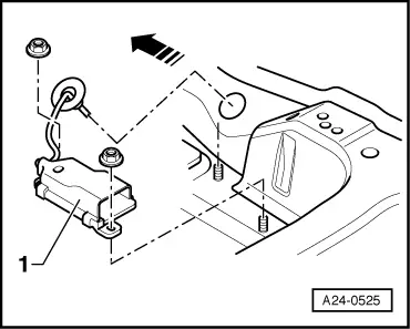
→ Fig.2    Fitting location of control unit for NOx sender -J583, under carpet under driver's seat; control unit for NOx sender -J583 is permanently connected to NOx sender -G295 via a cable. Control unit for NOx sender can only be accessed after removal of B-pillar trim on driver's side, rear seat bench and driver's seat. This work is described in Workshop Manual "General Body Repairs, Interior".

  •     1 -    Control unit for NOx sender -J583 ("NOx" means nitrogen oxide); arrow indicates direction of travel.
 
A24-0526

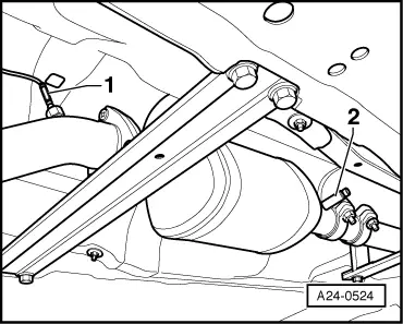
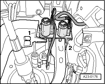
→ Fig.3    Fitting location of -G83

  •     1 -    Coolant temperature sender - radiator outlet -G83 (accessed from below, next to air conditioner compressor)

 
A24-0431

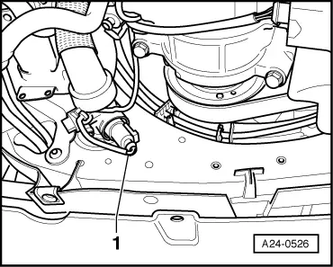
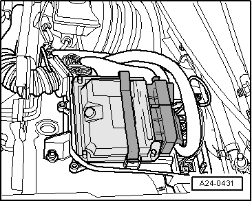
→ Fig. 4    Fitting location of engine control unit in plenum chamber electronics box

 
A23-0176

→ Fig. 5    Fitting location of brake light switch -F, brake pedal switch -F47 and clutch pedal switch -F36

  •     1 -    Brake light switch -F, brake pedal switch -F47
  •     2 -    Clutch pedal switch -F36

Note:

Switches are only to be fitted once so as to ensure a firm fit.

Switch adjustment:

=> Brake System; Repair Group 46

 
A24-0204

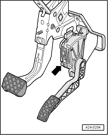
→ Fig. 6    Fitting location of accelerator pedal position sender -G79 and accelerator pedal position sender 2 -G185

Dismantling and assembling air cleaner > < Technical data