Audi Workshop Service and Repair Manuals
HOME
FEATURES
MENU
INDEX
ABOUT US
Ignition system, glow plug system >
< Technical data
A4 Cabriolet Mk2
Power unit
Motronic injection and ignition system (4-cylinder) / Mixture preparation system, electronic inj.,Gas / Servicing injection system
Fitting locations overview
Motronic injection and ignition system (4-cylinder)
Servicing injection system
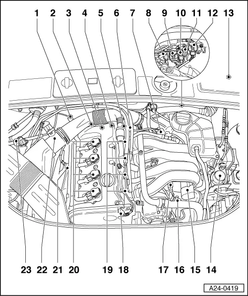
Fitting locations overview
Components A to F are not shown in the exploded drawing.
A - Brake light switch (F) and brake pedal switch (F47)
◆
In footwell on pedal bracket near brake pedal
B - Diagnostic connector
◆
In knee bar on driver's side
C - Fuel pump relay
◆
In micro central electrics behind storage compartment on driver's side, relay position 4
D - Clutch pedal switch (F36)
◆
In footwell on pedal bracket near clutch pedal
E - Accelerator pedal sender (G79) and accelerator pedal sender 2 (G185)
◆
In footwell on accelerator pedal (both senders are fitted in one housing)
F - EPC warning lamp
◆
In dash panel insert
Lambda probe (after catalytic converter) -G130 - 55 Nm
Secondary air inlet valve
-N112
Coolant temperature sender -G62
◆
Tightening torque for securing bolts: 9 Nm.
Camshaft adjustment valve 1
(N205)
Engine speed sender -G28
Fuel pressure regulator
Throttle valve control part -J338
◆
With throttle valve drive -G186, angle sender for throttle valve drive -G187 and angle sender 2 for throttle valve drive -G188
3 pin connector
◆
For knock sensor 1 -G61
4 pin connector
◆
For lambda probe (after catalytic converter) -G130 and lambda probe heating -Z29
3 pin connector
◆
For engine speed sender -G28
3 pin connector
◆
For knock sensor 2 -G66
6 pin connector
◆
For lambda probe (before catalytic converter) -G39 and lambda probe heating -Z19 (black)
Engine control unit -J361
◆
Located in electronics box in plenum chamber (left side)
13 - Secondary air pump relay -J299
◆
Located in electronics box in plenum chamber (left side)
13 - Voltage supply relay for engine control unit
◆
Located in electronics box in plenum chamber (left side)
Vacuum pump for brake servo
Vacuum unit for intake manifold change-over function
Intake manifold change-over valve -N156
Intake air temperature sender (G42)
Phase sensor (Hall sender) -G40
Injectors (N30...N33)
Ignition coils
Lambda probe (before catalytic converter) -G39 - 55Nm
Air mass meter -G70
Activated charcoal filter solenoid valve 1 -N80
Power unit
Motronic injection and ignition system (4-cylinder) / Mixture preparation system, electronic inj.,Gas / Servicing injection system
Fitting locations overview
Ignition system, glow plug system >
< Technical data