audi Workshop Repair Guides

Audi Workshop Service and Repair Manuals

Dismantling and assembling air cleaner Engine code letters: AMM, BDV > < Exploded view of fitting locations Engine code letters: AMM, BDV
Motronic injection and ignition system (6-cyl.)
Servicing Motronic injection system
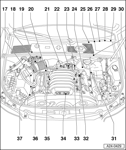
Exploded view of fitting locations Engine code letters: ASN, BBJ

Components A to D are not illustrated in the exploded view.

  •     A -    Accelerator position sender -G79 and accelerator pedal position sender 2 -G185
    • ◆ Fitting location
      => Fig. 24-22
  •     B -    Brake light switch -F and brake pedal switch -F47
    • ◆ Fitting location
      => Fig. 24-23
  •     C -    Clutch pedal switch -F36
    • ◆ Fitting location
      => Fig. 24-23
  •     D -    Engine control unit and relays in plenum chamber electronics box
    • ◆ Fitting locations =>Fig. 24-24
 
A24-0445
  • Activated charcoal filter solenoid valve -N80
  • Air-mass meter -G70
    • ◆ With intake-air temperature sender
      -G42
  • Hall sender 3 -G300
    • ◆ For exhaust camshaft
    • ◆ Bank 1
  • Hall sender -G40
    • ◆ For inlet camshaft
    • ◆ Bank 1
  • Brake servo pressure sensor -G294
    • ◆ For vehicles with automatic gearbox
  • Hall sender 2 -G163
    • ◆ For inlet camshaft
    • ◆ Bank 2
 
A24-0445
  • Hall sender 4 -G301
    • ◆ For exhaust camshaft
    • ◆ Bank 2
  • Ignition coils with output stage, bank 2
    • ◆ Cylinder 4 -N292
    • ◆ Cylinder 5 -N323
    • ◆ Cylinder 6 -N324
  • Electronics box in plenum chamber
    • ◆ Fitting locations =>Fig. 24-24
    • ◆ Fitting location for Motronic current supply relay -J271
    • ◆ Fitting location for secondary air pump relay -J299
    • ◆ Fitting location for fuse S130 for secondary air pump
    • ◆ Fitting location for relay for brake servo pump -J569
 
A24-0445
  • Brake servo pump -V192
    • ◆ For vehicles with automatic gearbox
  • Camshaft adjustment valve 2, inlet
    -N208
    Exhaust camshaft control valve 2 -N319
    • ◆ Bank 2
  • Injectors, bank 2
    • ◆ Cylinder 4 -N33
    • ◆ Cylinder 5 -N83
    • ◆ Cylinder 6 -N84
    • ◆ Removing and installing
  • Injectors, bank 1
    • ◆ Cylinder 1 -N30
    • ◆ Cylinder 2 -N31
    • ◆ Cylinder 3 -N32
    • ◆ Removing and installing
      => Page 24-65
 
A24-0445
  • Camshaft adjustment valve 1, inlet
    -N205
    Exhaust camshaft control valve 1 -N318
    • ◆ Bank 1
  • Ignition coils with output stage, bank 1
    • ◆ Cylinder 1 -N70
    • ◆ Cylinder 2 -N127
    • ◆ Cylinder 3 -N291
  • Secondary air pump motor -V101
 
A24-0429
  • Lambda probe -G39 and Lambda probe heater -Z19
    • ◆ Bank 1, probe 1
    • ◆ Continuous-action Lambda probe
  • Holder for connectors
    • ◆ For right side of vehicle
    • ◆ Assignment
      => Fig. 24-24
  • Lambda probe after catalyst -G130 and Lambda probe 1 heater after catalyst -Z29
    • ◆ Bank 1, probe 2
 
A24-0429
  • Coolant temperature sender -G62
    • ◆ With coolant temperature sender -G2
    • ◆ For engine control unit
    • ◆ At coolant pipe behind cylinder head, bank 1
    • ◆ Dissipate cooling system pressure if necessary prior to removal
  • Throttle valve control part -J338
    • ◆ With throttle valve drive -G186, throttle valve drive angle sender 1 -G187 and throttle valve drive angle sender 2 -G188
  • Secondary air inlet valve -N112
  • Engine speed sender -G28
    • ◆ In gearbox housing above ring gear
 
A24-0429
  • Holder for connectors
    • ◆ For left side of vehicle
    • ◆ Assignment =>Fig. 24-25
  • Accelerator position sender -G79 and accelerator pedal position sender
    -G185
    • ◆ Fitting location
      => Fig. 24-22
  • Fuel pump relay -J17
    • ◆ Fitting location =>Fig. 24-22
  • Brake light switch -F and brake pedal switch -F47
    • ◆ Fitting location
      => Fig. 24-23
 
A24-0429
  • Clutch pedal switch -F36
    • ◆ Fitting location
      => Fig. 24-23
  • Dash panel insert
    • ◆ With electric throttle control fault lamp -K132 ("EPC" warning lamp)
    • ◆ With exhaust emissions warning lamp -K83
  • Lambda probe 2 after catalyst -G131 and Lambda probe 2 heater after catalyst -Z30
    • ◆ Bank 2, probe 2
 
A24-0429
  • Lambda probe 2 -G108 and Lambda probe 2 heater -Z28
    • ◆ Bank 2, probe 1
    • ◆ Continuous-action Lambda probe
  • Fuel pressure regulator
    • ◆ Checking => Page 24-51
  • Knock sensor 2 -G66
    • ◆ Bank 2
    • ◆ Beneath intake manifold
  • Intake manifold changeover valve
    -N156
 
A24-0429
  • Knock sensor 1 -G61
    • ◆ Bank 1
    • ◆ Beneath intake manifold
  • Not installed
    • ◆ For hot countries only
  • Earth connection
    • ◆ At engine support on right
 
A24-0204

→ Fig. 1    Fitting location of accelerator position sender -G79 and accelerator pedal position sender -G185

  • ◆ Integrated in accelerator pedal module -arrow-

Note:

Accelerator position sender -G79 and accelerator pedal position sender 2 -G185 are integrated into accelerator pedal module and cannot be replaced separately.

Removing and installing accelerator pedal module

=> Fuel Supply System - Petrol Engines; Repair Group 20

 
A20-0801

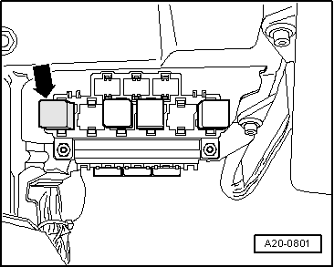
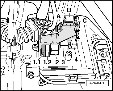
→ Fig. 2    Fitting location of fuel-pump relay -J17

  • ◆ On 9-position relay carrier on left of driver's footwell, position 1 -arrow-
 
A23-0176

→ Fig. 3    Fitting location of brake light switch -F, brake pedal switch -F47 and clutch pedal switch -F36

  •     1 -    Clutch pedal switch -F36
  •     2 -    Brake light switch -F, brake pedal switch -F47

Removing and installing switches

=> Brake System; Repair Group 46

=> Manual Gearbox; Repair Group 30

 
A24-0431

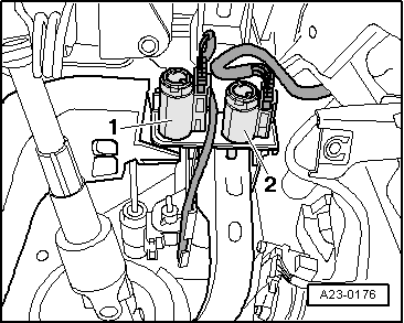
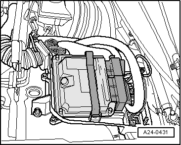
→ Fig. 4    Fitting location of engine control unit in plenum chamber electronics box

 
A24-0430

→ Fig. 5    Fitting locations in plenum chamber electronics box

  •     1.1 -    Continued coolant circulation relay -J151 (hot countries only)
  •     1.2 -    Not used
  •     2 -    Motronic current supply relay -J271
  •     3 -    Secondary air pump relay -J299
  •     4 -    Relay for automatic gearbox
  •     A -    Fuse S282 for engine electronics
  •     B -    Secondary air pump fuse S130
  •     C -    Not used

 
A10-1003

→ Fig. 6    Assignment of holder for connectors - right side of vehicle

  •     1 -    Connector (4-pin AMM, BDV) (6-pin ASN), black
    • For Lambda probe -G39 and Lambda probe heater -Z19 (bank 1, probe 1)
  •     2 -    3-pin blue connector
    • For knock sensor 1 -G61
  •     3 -    4-pin green connector
    • For Lambda probe after catalyst -G130 and Lambda probe 1 heater after catalyst -Z29 (bank 1, probe 2)
  •     4 -    3-pin black connector
    • For terminal 50
 
A10-1002

→ Fig. 7    Assignment of holder for connectors - left side of vehicle

  •     1 -    4-pin brown connector
    • For Lambda probe 2 after catalyst -G131 and Lambda probe 2 heater after catalyst -Z30 (bank 2, probe 2)
  •     2 -    3-pin grey connector
    • For engine speed sender -G28
  •     3 -    3-pin blue connector
    • For knock sensor 2 -G66
  •     4 -    Connector (4-pin AMM, BDV) (6-pin ASN), black
    • For Lambda probe 2 -G108 and Lambda probe 2 heater -Z28 (bank 2, probe 1)

 
A10-0989

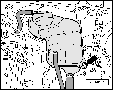
Note:

→ To gain access to connectors, remove cover on left of engine compartment, disconnect wire to coolant shortage indicator switch at bottom of expansion tank, screw out bolt -arrow- of coolant expansion tank and lay aside. Leave coolant hoses -1...3- connected.

Dismantling and assembling air cleaner Engine code letters: AMM, BDV > < Exploded view of fitting locations Engine code letters: AMM, BDV