audi Workshop Repair Guides

Audi Workshop Service and Repair Manuals

Checking fuel pressure regulator and holding pressure > < Technical data
Motronic injection and ignition system (8-cyl.)
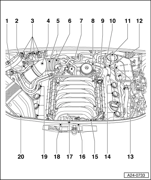
Servicing Motronic injection system
Exploded view of fitting locations

Components A to I are not shown in exploded view.

  •     A -    "MIL" exhaust emissions warning lamp
    • ◆ In dash panel insert
      (Function of lamp
    • ◆ =>Fig. 24-11)
  •     B -    "EPC" warning lamp
    • ◆ In dash panel insert
      (Function of lamp
    • ◆ =>Fig. 2, Page 24-12
  •     C -    Accelerator pedal position senders (-G79) and (-G185)
    • ◆ In footwell at accelerator pedal (both senders share same housing)
    • ◆ =>Fig. 24-14
  •     D -    Fuel-pump relay (-J17)
    • ◆ In 9-position relay carrier behind driver's storage compartment, relay position 1
    • ◆ =>Fig. 24-15
  •     E -    Brake light switch (-F) and brake pedal switch (-F47)
    • ◆ In footwell at pedal bracket next to brake pedal
    • ◆ =>Fig. 24-15
  •     F -    Clutch pedal switch (-F36)
  •     G -    Engine control unit (-J220) and relays in plenum chamber electronics box
    • ◆ Fitting locations =>Fig.24-16
  •     H -    Diagnostic connector
    • ◆ In driver's knee restraint
 
A24-0733
  • Activated charcoal filter system solenoid valve 1 (-N80)
  • Air mass meter (-G70) with intake-air temperature sender (-G42)
  • Connector console
    • ◆ Pin assignment
    • ◆ =>Fig. 24-17
  • Inlet camshaft timing adjustment valve 1 (-N205)
  • Hall sender (-G40)
    • ◆ Cylinder bank 1
    • ◆ =>Fig. 24-18
 
A24-0733
  • Coolant temperature sender (-G62)
    • ◆ At coolant pipe behind cylinder head, bank 1
    • ◆ =>Fig. 24-18
  • Throttle valve control part (-J338)
    • ◆ With throttle valve drive (-G186), throttle valve drive angle sender 1 (-G187) and throttle valve drive angle sender 2 (-G188)
    • ◆ =>Fig. 24-18
  • Oil pressure switch (-F1)
  • Fuel pressure regulator
 
A24-0733
  • Hall sender 2 (-G163)
    • ◆ Cylinder bank 2
    • ◆ =>Fig. 24-18
  • Connector console
    • ◆ Pin assignment
    • ◆ =>Fig. 24-17
  • Inlet camshaft timing adjustment valve 2 (-N208)
  • Engine speed sender -G28
    • ◆ In gearbox housing above ring gear
  • Ignition coils with output stages
    • ◆ Cylinder bank 2
  • 3-pin connector
    • ◆ For knock sensor 3 (-G198)
    • ◆ For knock sensor 4 (-G199)
    • ◆ =>Fig. 24-18
 
A24-0733
  • Secondary air inlet valve (-N112)
  • Intake-manifold changeover valve (-N156)
  • 3-pin connector
    • ◆ For knock sensor 1 (-G61)
    • ◆ For knock sensor 2 (-G66)
    • ◆ =>Fig. 24-18
  • Ignition coils with output stages
    • ◆ Cylinder bank 1
  • Secondary air pump motor (-V101)
    • ◆ Beneath right longitudinal member
    • ◆ =>Fig. 24-19
 
A24-0732

Fig.1    MIL exhaust emissions warning lamp

Emission-specific faults recognised by the engine control unit are indicated by activating the exhaust emissions warning lamp.

→ → Fitting location of exhaust emissions warning lamp (CHECK)

Note:

Exhaust emissions warning lamp may flash or be constantly lit. Fault memory is always to be interrogated.

Flashing of exhaust emissions warning lamp

  • ◆ A fault has been detected which will cause catalytic converter damage in this driving status. In such cases, vehicle is only to be driven at reduced power (until MIL goes out or lights constantly) and fault is to be rectified as quickly as possible.

Constant lighting of exhaust emissions warning lamp

  • ◆ A fault detrimental to emissions has occurred. Interrogate engine control unit or automatic gearbox fault memory.
  • ◆ In the event of engine running problems or a customer complaint without lighting of the exhaust emissions warning lamp, check operation of warning lamp and then interrogate fault memory, as faults may also have been stored which do not immediately activate the exhaust emissions warning lamp.

Fig.2    EPC warning lamp

 
A24-0732

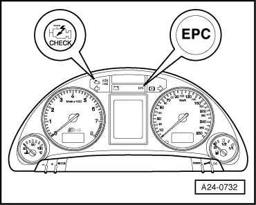
"EPC" is the abbreviation for Electronic Power Control, in other words electronic engine output control (electronic throttle).

→ Fitting location of EPC warning lamp

The engine control unit switches on the EPC lamp when the ignition is switched on.

After starting engine, engine control unit checks all components of relevance to operation of electronic throttle system.

During this component check, the EPC lamp lights for approx. 3 seconds. The lamp lights continuously if a fault is already established in the course of this check.

If faults in the electronic throttle system are detected during engine operation, the engine control unit activates the EPC lamp. At the same time, an entry is made in the engine control unit fault memory.

 
A24-0627

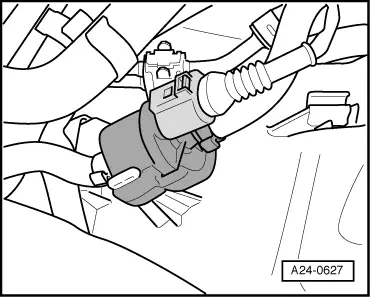
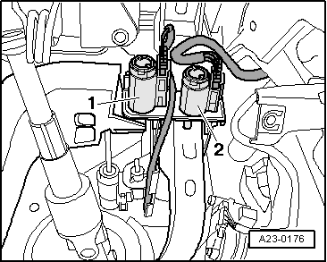
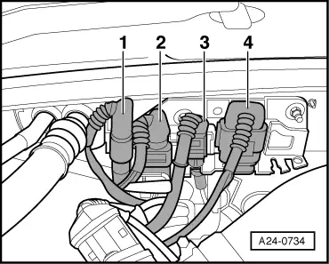
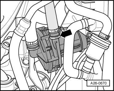
→ Fig.3    Activated charcoal filter system solenoid valve 1 (-N80)

 
A24-0204

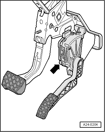
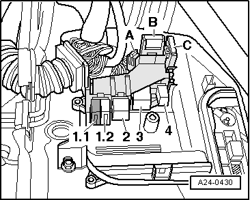
→ Fig.4    Fitting location of accelerator pedal position sender -G79 and accelerator pedal position sender 2 -G185

  • ◆ Integrated into accelerator pedal module -arrow-
 
A23-0176

→ Fig. 5    Fitting location of brake light switch -F, brake pedal switch -F47 and clutch pedal switch -F36

  •     1 -    Clutch pedal switch -F36
  •     2 -    Brake light switch -F, brake pedal switch -F47

Note:

Switches are only to be fitted once so as to ensure a firm fit.

Switch adjustment:

=> Manual gearbox; Repair Group 30

=> Brake system; Repair Group 46

 
A20-0801

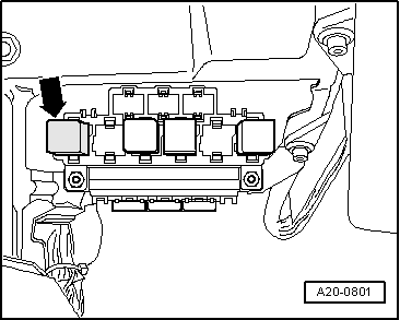
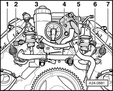
→ Fig.6    Fitting location of fuel pump relay -J17

  • ◆ On 9-position relay carrier on left of driver's footwell, position 1 -arrow-
 
A24-0430

→ Fig. 7    Fitting locations in plenum chamber electronics box

  •     1.1 -    Continued coolant circulation relay -J151 (hot countries only)
  •     1.2 -    Not used
  •     2 -    Motronic current supply relay -J271
  •     3 -    Secondary air pump relay -J299
  •     4 -    Relay for automatic gearbox
  •     A -    Engine electronics fuse S282
  •     B -    Secondary air pump fuse S130
  •     C -    Not used

 
A24-0431

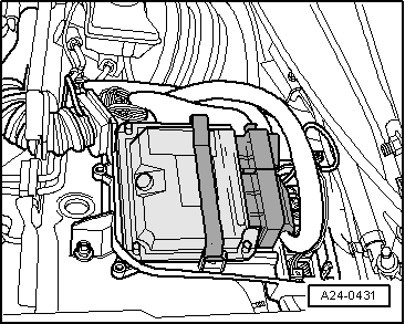
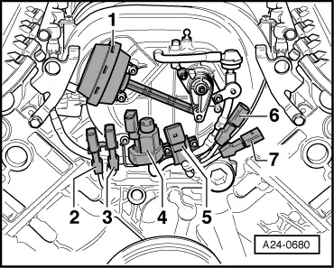
→ Fig. 8    Fitting location of engine control unit in plenum chamber electronics box

 
A24-0734

→ Fig.9    Assignment of holder for connectors (right side)

  •     1 -    6-pin connector for lambda probe (-G39) and lambda probe heater (-Z19) upstream of catalytic converter, bank 1
  •     2 -    Connector for starter (terminal 50) and alternator
  •     3 -    2-pin connector for camshaft timing control, bank 1
  •     4 -    4-pin connector for lambda probe after catalyst (-G130) and lambda probe 1 heater after catalyst (-Z29), bank 1

 
A10-1002

→ Fig.10        Connector console beneath coolant expansion tank

  •     1 -    4-pin connector for lambda probe 2 after catalyst (-G131) and lambda probe 2 heater after catalyst (-Z30), bank 2
  •     2 -    3-pin grey connector for engine speed sender (-G28)
  •     3 -    2-pin connector for camshaft timing control, bank 2
  •     4 -    6-pin connector for lambda probe 2 (-G108) and lambda probe 2 heater (-Z28) upstream of catalytic converter, bank 2
 
A24-0681

→ Fig.11        Rear view

  •     1 -    Inlet camshaft timing adjustment valve 2 (-N208)
  •     2 -    Hall sender 2 (-G163), cylinder bank 2
  •     3 -    Oil pressure switch (-F1)
  •     4 -    Throttle valve control part (-J338)
  •     5 -    Coolant temperature sender (-G62)
  •     6 -    Hall sender (-G40), cylinder bank 1
  •     7 -    Inlet camshaft timing adjustment valve 1 (-N205)

 
A24-0680

→ Fig.12        Front view

  •     1 -    Vacuum unit for intake manifold changeover
  •     2 -    Knock sensor 1 (-G61)
  •     3 -    Knock sensor 2 (-G66)
  •     4 -    Intake manifold changeover valve (-N156)
  •     5 -    Secondary air inlet valve (-N112)
  •     6 -    Knock sensor 3 (-G198)
  •     7 -    Knock sensor 4 (-G199)
 
A26-0670

→ Fig.13        Secondary air pump motor (-V101)

Beneath right longitudinal member

Checking fuel pressure regulator and holding pressure > < Technical data