audi Workshop Repair Guides

Audi Workshop Service and Repair Manuals

Removing and installing lambda probe upstream of catalytic converter, bank 1 (right) > < Exploded view of intake manifold
Motronic injection and ignition system (8-cyl.)
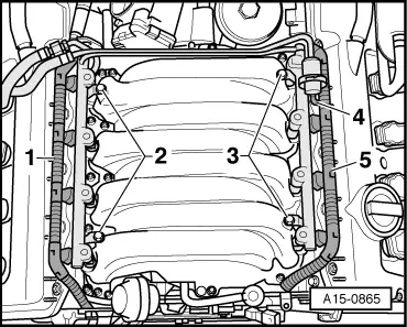
Servicing Motronic injection system
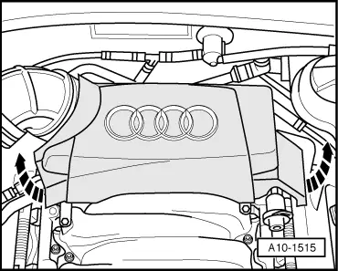
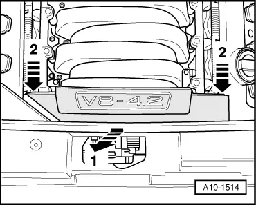
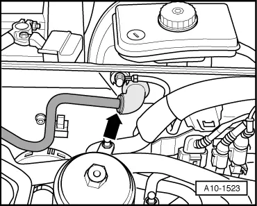
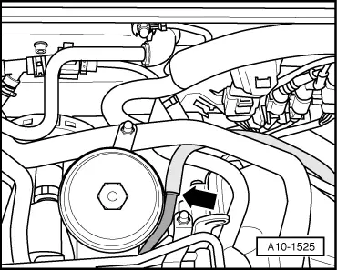
Removing and installing intake manifold
 
A10-1515

Removing

Note:

All cable ties unfastened or cut open on removal are to be re-attached in same position on installation.

  • ‒ Move lock carrier to service position.

=> Engine, Mechanics; Repair Group 13

  • ‒ → Detach rear engine cover -arrows-.

 
A10-1514
  • ‒ → Detach front engine cover -arrows 1 and 2-.
 
A10-1523
  • ‒ → Detach vacuum pipe -arrow- to brake servo at bulkhead.

 
A10-1525
  • ‒ → Detach vacuum pipe -arrow- to vacuum reservoir.
 
A10-1458
  • ‒ → Disconnect vacuum hose -arrow- at intake manifold.

 
A10-0891
  • ‒ → Unplug connector -1- at throttle valve control part -J338.
  • ‒ Detach vacuum hose -2-.
  • ‒ Remove air hose -3-.
  • ‒ Detach crankcase breather hose -4- at intake manifold.
 
A15-0864
  • ‒ → Pull connectors -1 ... 4- forwards off holders at intake manifold.

Note:

Connectors are not to be unplugged.

 
A15-0873
  • ‒ → Disconnect vacuum hose -arrow- at T-piece.
 
A15-0865
  • ‒ → Unplug connector consoles -1- and -5- at injectors.
  • ‒ Detach vacuum pipe -4- at fuel pressure regulator.
  • ‒ Screw out retaining bolts -2- and -3- of fuel rail.
  • ‒ Lift fuel rail together with injectors evenly off intake manifold and place it on a clean cloth in the engine compartment.

Note:

Make sure injectors removed are properly protected against contamination.

 
A15-0866
  • ‒ → Unscrew rear left engine lifting eye -arrows-.
 
A15-0867
  • ‒ → Unscrew and take out intake manifold -arrows-.

Note:

Seal intake ducts in cylinder heads with clean cloths.

Installing

Install in reverse order, paying attention to the following:

Notes:

  • ◆ Replace gaskets and O-rings.
  • ◆ Re-attach all cable ties at same location on installation.
  • ◆ Secure all hose connections with standard hose clamps.

=> Parts List

 
A15-0350
  • ‒ → Screw out locating bolts -1- and replace intake manifold gaskets.
  • ‒ Pay attention to locating pins -2- when fitting intake manifold.

 
A15-0867
  • ‒ → Screw on intake manifold diagonally and in stages -arrows-.
  • ‒ Install lock carrier with attachments.

=> General body repairs, exterior; Repair Group 50

 
A13-0633
  • ‒ → Allow stop for torque reaction support to settle on rubber buffer for torque reaction support and tighten bolts -arrows- to 28 Nm.
  • ‒ Install front bumper.

=> General body repairs, exterior; Repair Group 63; Front bumper

  • ‒ Adjust headlights.

=> Electrical system; Repair Group 94; Servicing headlights; Headlight adjustment

Tightening torques

Component

Nm

Locating bolt to cylinder head

0.6

Intake manifold to cylinder head

10

Engine lifting eye to cylinder head

22

Fuel rail to intake manifold

10

Removing and installing lambda probe upstream of catalytic converter, bank 1 (right) > < Exploded view of intake manifold