A4 Cabriolet Mk2
|
Servicing Motronic injection system
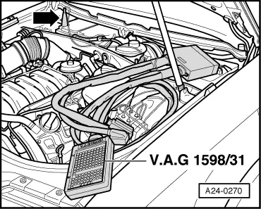
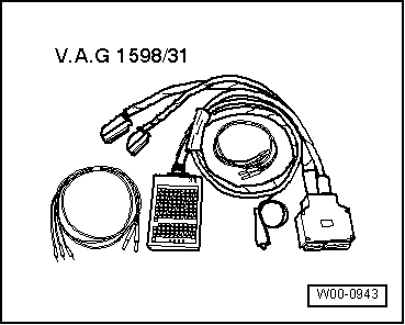
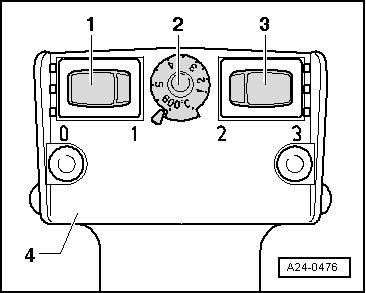
Wiring and component check using test box V.A.G 1598/31
|
 |
|
|
Notes:
Attention:
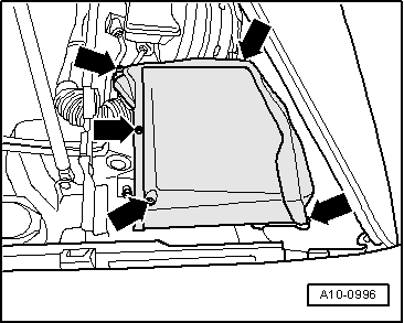
So as not to destroy electronic components, select required measuring range before connecting test leads and observe test conditions. Connecting up test box V.A.G 1598/31
|
 |
|
|
 |
|
|
 |
|
|
 |
|
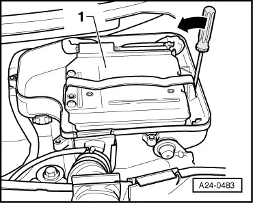
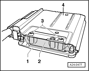
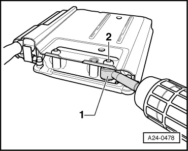
Note: Item -1- in illustration shows engine control unit with protective enclosure. |
 |
|
|
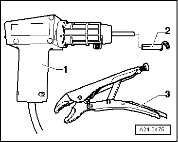
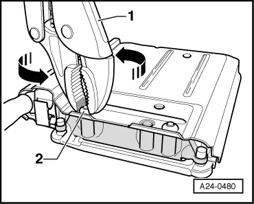
→ To render access to the connectors on the engine control unit more difficult, the engine control unit -1- is bolted by way of a catch -2- and shear bolts -3- to a protective enclosure -4-. Locking fluid is applied to thread of shear bolts to make bolts more difficult to screw out. Engine control unit must be separated from protective enclosure to unplug connectors from engine control unit (e.g. when connecting up test box or replacing engine control unit). This procedure is described in the following. Tools required: |
 |
|
Procedure: Attention:
To avoid damaging (scorching) wires, connectors, insulation and control units, always adhere exactly to the following operations and observe operating instructions for hot-air blower. |
|
|
|
 |
|
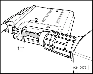
Note: Then use hot-air blower to heat thread of catch into which shear bolts are screwed. This operation is designed to reduce the inhibiting action of the locking fluid on the shear bolt thread to make it easier to screw out the shear bolts afterwards. Attention:
Heating the thread of the catch also greatly increases the temperature of the shear bolts and protective enclosure components. Take care to avoid burns. It is also important to ensure that only the thread is heated and none of the surrounding components if at all possible (these should be covered if necessary). |
 |
|
|
 |
|
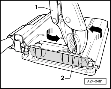
Employ exactly the same procedure for the second shear bolt, taking particular care to avoid the control unit connectors in the immediate vicinity. |
 |
|
|
 |
|
Engine control unit can now be separated from protective enclosure.
|