audi Workshop Repair Guides

Audi Workshop Service and Repair Manuals

Removing and installing high-pressure pump > < Removing and installing injectors
Checking fuel pressure and residual pressure (up to high-pressure pump)
Special tools and workshop equipment required
   
t  K-Jetronic pressure tester -V.A.G 1318-
t  Adapter set -V.A.G 1318/10-12-
  W00-0577
t  Remote control -V.A.G 1348/3A- for V.A.G 1348 with adapter cable -V.A.G 1348/3-3-
t  Fuel-resistant measuring container
Test conditions
l  Battery voltage at least 12.5 V
l  Fuel filter OK
l  Fuel tank at least 1/4 full.
l  Fuel pump control unit -J538- OK; checking → Rep. Gr.20.
l  Ignition off.
Checking fuel pressure
Saloon models with front-wheel drive:
–  Detach trim in luggage compartment.
–  If necessary, fold forward right backrest of rear seat bench.
Avant models with front-wheel drive:
–  Remove left-side section of backrest (1/3 section) → Rep. Gr.72.
–  Remove left-side trim in luggage compartment and anti-soiling tray → Rep. Gr.70.
  W00-0688
All models with front-wheel drive:
–  If necessary, fold forward right backrest of rear seat bench.
–  Take out luggage compartment floor trim.
–  Unscrew cover for flange -arrows-.
  A20-0774
–  Carefully release electrical connector from flange -arrow- and unplug.
  A20-1226
Vehicles with four-wheel drive:
–  Remove rear seat bench → Rep. Gr.72.
–  Unscrew cover for flange (right-side) -arrows-.
  A20-0803
–  Carefully release electrical connector from flange -arrow- and unplug.
  A20-10018
All models:
–  Connect remote control for V.A.G 1348 -V.A.G 1348/3A- to contact -1- using adapter cable -V.A.G 1348/3-3- and test lead from auxiliary measuring set -V.A.G 1594C-.
–  Tape off 2nd connector contact of adapter cable -V.A.G 1348/3-3- with insulating tape -arrow- to prevent short circuits.
–  Move switch of remote control -V.A.G 1348/3A- for V.A.G 1348 to front of engine compartment.
–  Connect contact -4- to body earth via an improvised auxiliary lead.
–  Connect crocodile clamp to battery “+”.
  A20-10084
–  Pull off engine cover (rear) -arrows-.
  WARNING
t  The fuel system operates under high pressure. The pressure in the high-pressure part of the injection system must be reduced to a residual pressure prior to opening the system → Chapter.
t  A clean cloth must then be wrapped around the connection and the residual pressure dissipated by carefully loosening the connection.
  A10-1515
–  Disconnect fuel line -arrow-.
  A20-1261
–  Connect K-Jetronic pressure tester -V.A.G 1318- with adapters -V.A.G 1318/11- and -V.A.G 1318/12- to fuel pipe.
–  Fit auxiliary hose -arrow- onto pressure gauge and hold it into container to catch any escaping fuel.
–  Open cut-off valve on pressure tester. Lever points in direction of flow.
–  Bleed fuel system by pressing remote control briefly.
  A20-1266
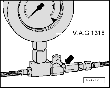
–  Close cut-off tap on pressure gauge. Lever is at right angle to direction of flow -arrow-.
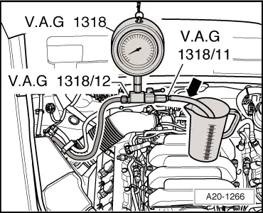
–  Press switch on remote control until pressure gauge shows no further increase in pressure.
l  Specification: approx. 6 bar
If specification is not obtained:
–  Check fuel pump delivery rate → Rep. Gr.20.
Checking residual pressure
–  Check leak-tightness and residual pressure by watching the drop in pressure on the pressure gauge.
l  After 10 minutes pressure should still be at least 3.75 bar.
If the residual pressure drops below 3.75 bar:
t  Check union between pressure gauge and fuel line for leaks.
t  Test pressure gauge for leaks.
t  Check fuel lines and their connections for leaks.
t  Renew fuel filter with integral fuel pressure regulator → Rep. Gr.20.
t  Renew fuel pump → Rep. Gr.20.
Assembly is carried out in the reverse order; note the following:
  Note
Before removing the pressure tester, release the fuel pressure by opening the cut-off valve. Hold a container under the connection.
Tightening torque
  N24-0618
ComponentNm
Fuel line to fuel rail28


Removing and installing high-pressure pump > < Removing and installing injectors