
A4 Cabriolet Mk2
| Removing and installing intake manifold (bottom section) with fuel rail |
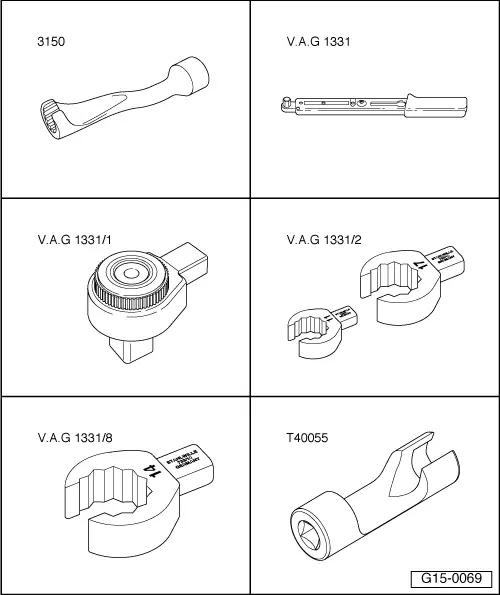
| Special tools and workshop equipment required |
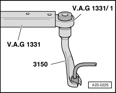
| t | Socket, 14 mm -3150- |
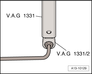
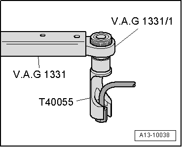
| t | Torque wrench -V.A.G 1331- |
| t | Ratchet -V.A.G 1331/1- |
| t | Tool insert (open-end ring spanner, 17 mm) -V.A.G 1331/2- |
| t | Socket insert AF 14, flared ring spanner -V.A.G 1331/8- |
| t | Socket -T40055- |
|
|
 Note
Note
|
|
 WARNING
|
|
Note
Note
|
|
Note
|
|
|
|
|
|
|

|
|
|
|
|
|
|
| Component | Nm | |
| Intake manifold (bottom section) to cylinder head | 9 | |
| High-pressure pipes to: | High-pressure pump | 25 |
| Fuel rail | 25 | |