audi Workshop Repair Guides

Audi Workshop Service and Repair Manuals

Removing and installing engine speed sender G28 > < Intake manifold - exploded view
Removing and installing intake manifold
   
Removing
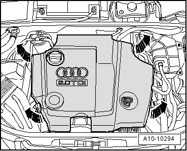
–  Pull off engine cover panel -arrows-.
  A10-10294
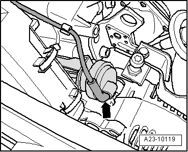
–  If fitted, disconnect vacuum hose from vacuum unit for intake manifold flap -arrow- and move vacuum hose aside.
  A23-10119
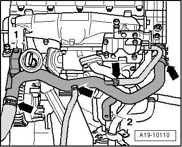
–  Remove bolts -1- and -2-.
  Note
Leave coolant hoses -arrows- connected.
  A19-10110
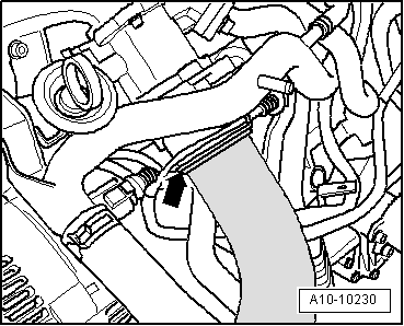
–  Remove air intake hose at intake manifold flap motor -V157- by lifting retaining clip -arrow- slightly.
  A10-10230
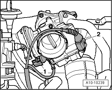
–  Unplug electrical connectors at exhaust gas recirculation valve -N18- / exhaust gas recirculation potentiometer -G212--item 1- and at intake manifold flap motor -V157--item 2-.
  A10-10239
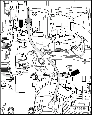
–  Unscrew bolt -top arrow-.
  A17-0349
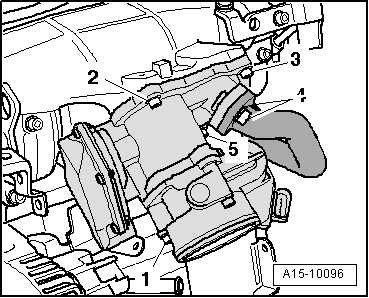
–  Remove bolts -1 ... 5- and take out exhaust gas recirculation valve -N18- / exhaust gas recirculation potentiometer -G212- together with intake manifold flap motor -V157-.
  A15-10096
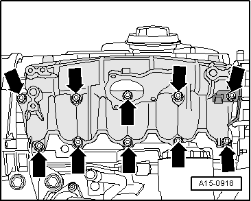
–  Unbolt intake manifold -arrows-.
Installing
Installation is carried out in the reverse order; note the following:
  Note
Renew gaskets and seals.
  A15-0918
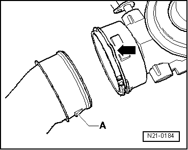
–  When installing air intake hoses with plug-in connectors, ensure that the securing clip -arrow- engages audibly on the retaining lug -A-.
Tightening torques
  N21-0184
ComponentNm
Intake manifold to cylinder head22
Exhaust gas recirculation valve -N18-/exhaust gas recirculation potentiometer -G212- to intake manifold10
Connecting pipe to exhaust gas recirculation valve -N18-/exhaust gas recirculation potentiometer -G212-22
Intake manifold flap motor -V157- to exhaust gas recirculation valve -N18-/exhaust gas recirculation potentiometer -G212-10
Coolant pipeEngine lifting eye10
(top) to:Oil filter bracket10
Guide tube for oil dipstick to engine lifting eye10


Removing and installing engine speed sender G28 > < Intake manifold - exploded view